What is Digital Signal Processing?
DSP manipulates different types of signals with the intention of filtering, measuring, or compressing and producing analog signals. Analog signals differ by taking information and translating it into electric pulses of varying amplitude, whereas digital signal information is translated into binary format where each bit of data is represented by two distinguishable amplitudes. Another noticeable difference is that analog signals can be represented as sine waves and digital signals are represented as square waves. DSP can be found in almost any field, whether it’s oil processing, sound reproduction, radar and sonar, medical image processing, or telecommunications– essentially any application in which signals are being compressed and reproduced.

So what exactly is digital signal processing? The digital signal process takes signals like audio, voice, video, temperature, or pressure that have already been digitized and then manipulates them mathematically. This information can then be represented as discrete time, discrete frequency, or other discrete forms so that the information can be digitally processed. An analog-to-digital converter is needed in the real world to take analog signals (sound, light, pressure, or temperature) and convert them into 0’s and 1’s for a digital format.
A DSP contains four key components:
Computing Engine: Mathematical manipulations, calculations, and processes by accessing the program, or task, from the Program Memory and the information stored in the Data Memory.
Data Memory: This stores the information to be processed and works hand in hand with program memory.
Program Memory: This stores the programs, or tasks, that the DSP will use to process, compress, or manipulate data.
I/O: This can be used for various things, depending on the field DSP is being used for, i.e. external ports, serial ports, timers, and connecting to the outside world.
Below is a figure of what the four components of a DSP look like in a general system configuration.

DSP FIlters
The Chebyshev filter is a digital filter that can be used to separate one band of frequency from another. These filters are known for their primary attribute, speed, and while they aren’t the best in the performance category, they are more than adequate for most applications. The design of the Chebyshev filter was engineered around the matematical technique, known as z-transform. Basically, the z-transform converts a discrete-time signal, made up of a sequence of real or complex numbers into a frequency domain representation. The Chebyshev response is generally used for achieving a faster roll-off by allowing ripple in the frequency response. These filters are called type 1 filters, meaning that the ripple in the frequency response is only allowed in the passband. This provides the best approximation to the ideal response of any filter for a specified order and ripple. It was designed to remove certain frequencies and allow others to pass through the filter. The Chebyshev filter is generally linear in its response and a nonlinear filter could result in the output signal containing frequency components that were not present in the input signal.
Why Use Digital Signal Processing?
To understand how digital signal processing, or DSP, compares with analog circuitry, one would compare the two systems with any filter function. While an analog filter would use amplifiers, capacitors, inductors, or resistors, and be affordable and easy to assemble, it would be rather difficult to calibrate or modify the filter order. However, the same things can be done with a DSP system, just easier to design and modify. The filter function on a DSP system is software-based, so multiple filters can be chosen from. Also, to create flexible and adjustable filters with high-order responses only requires the DSP software, whereas analog requires additional hardware.
For example, a practical bandpass filter, with a given frequency response should have a stopband roll-off control, passband tuning and width control, infinite attenuation in the stopband, and a response within the passband that is completely flat with zero phase shift. If analog methods were being used, second-order filters would require a lot of staggered high-Q sections, which ultimately means that it will be extremely hard to tune and adjust. While approaching this with DSP software, using a finite impulse response (FIR), the filter’s time response to an impulse is the weighted sum of the present and a finite number of previous input values. With no feedback, its only response to a given sample ends when the sample reaches the “end of the line”. With these design differences in mind, DSP software is chosen for its flexibility and simplicity over analog circuitry filter designs.
When creating this bandpass filter, using DSP is not a terrible task to complete. Implementing it and manufacturing the filters is much easier, as you only have to program the filters the same with every DSP chip going into the device. However, using analog components, you have the risk of faulty components, adjusting the circuit and program the filter on each individual analog circuit. DSP creates an affordable and less tedious way of filter design for signal processing and increases accuracy for tuning and adjusting filters in general.
ADC & DAC
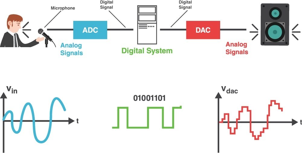
Electric equipment is heavily used in nearly every field. Analog to Digital Converters (ADC) and Digital to Analog Converters (DAC) are essential components for any variation of DSP in any field. These two converting interfaces are necessary to convert real world signals to allow for digital electronic equipment to pick up any analog signal and process it. Take a microphone for example: the ADC converts the analog signal collected by an input to audio equipment into a digital signal that can be outputted by speakers or monitors. While it is passing through the audio equipment to the computer, software can add echoes or adjust the tempo and pitch of the voice to get a perfect sound. On the other hand, DAC will convert the already processed digital signal back into the analog signal that is used by audio output equipment such as monitors. Below is a figure showing how the previous example works and how its audio input signals can be enhanced through reproduction, and then outputted as digital signals through monitors.

A type of analog to digital converter, known as the digital ramp ADC, involves a comparator. The value of the analog voltage at some point in time is compared with a given standard voltage. One way to achieve this is by applying the analog voltage to one terminal of the comparator and trigger, known as a binary counter, which drives a DAC. While the output of the DAC is implemented to the other terminal of the comparator, it will trigger a signal if the voltage exceeds the analog voltage input. The transition of the comparator stops the binary counter, which then holds the digital value corresponding to the analog voltage at that point. The figure below shows a diagram of a digital ramp ADC.

Applications of DSP
There are numerous variants of a digital signal processor that can execute different things, depending on the application being performed. Some of these variants are audio signal processing, audio and video compression, speech processing and recognition, digital image processing, and radar applications. The difference between each of these applications is how the digital signal processor can filter each input. There are five different aspects that varies from each DSP: clock frequency, RAM size, data bus width, ROM size, and I/O voltage. All of these components really are just going to affect the arithmetic format, speed, memory organization, and data width of a processor.
One well-known architecture layout is the Harvard architecture. This design allows for a processor to simultaneously access two memory banks using two independent sets of buses. This architecture can execute mathematical operations while fetching further instructions. Another is the Von Neumann memory architecture. While there is only one data bus, operations cannot be loaded while instructions are fetched. This causes a jam that ultimately slows down the execution of DSP applications. While these processors are similar to a processor used in a standard computer, these digital signal processors are specialized. That often means that, to perform a task, the DSPs are required to used fixed-point arithmetic.
Another is sampling, which is the reduction of a continuous signal to a discrete signal. One major application is the conversion of a sound wave. Audio sampling uses digital signals and pulse-code modulation for the reproduction of sound. It is necessary to capture audio between 20 – 20,000 Hz for humans to hear. Sample rates higher than that of around 50 kHz – 60 kHz cannot provide any more information to the human ear. Using different filters with DSP software and ADC’s & DAC’s, samples of audio can be reproduced through this technique.
Digital signal processing is heavily used in day-to-day operations, and is essential in


Comments are closed