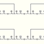
The double breaker-double bus configuration consists of two main buses, each normally energized. Electrically connected between the buses are two circuit breakers and, between the breakers, one circuit, as diagrammed in Figure 8.
Two circuit breakers are required for each circuit.
In the double breaker–double bus configuration, any circuit breaker can be removed from service without interruption of any circuits. Faults on either of the main buses cause no circuit interruptions. Circuit breaker failure results in the loss of only one circuit.
A typical bus configuration for a double breaker–double bus arrangement is shown in Figure 8.
 Figure 8 – Double Breaker-Double Bus Configuration
Use of the double breaker–double bus configuration is usually limited to large generating stations because of the high cost. The additional reliability afforded by this arrangement over the breaker-and-a-half scheme usually cannot be justified for conventional transmission or distribution substations.
Occasionally, at a generating station, one bay of a breaker-and-a-half arrangement is used as a double breaker–double bus arrangement for a generator terminal to provide equal access to either main bus.
Advantages
· Flexible operation.
· Very high reliability.
· Isolation of either main bus for maintenance without disrupting service.
· Isolation of any circuit breaker for maintenance without disrupting service.
· Double feed to each circuit.
· No interruption of service to any circuits from bus fault.
· Loss of only one circuit for breaker failure.
· All switching with circuit breakers.
Disadvantages
· This configuration carries a high cost.
· Two circuit breakers are required for each circuit.