
You build a small controller that turns on a lamp, a pump, or a solenoid. The microcontroller pin can produce a neat 3.3 V logic signal, but the load may need 12 V, several amperes, or connection to mains power. A switching device must bridge that gap safely.
At first, the choice can look simple: use a transistor for electronic switching, or use a relay because it has physical contacts. Yet the wrong choice can cause a noisy circuit, a hot component, welded contacts, unexpected resets, or an enclosure that is unsafe to touch.
Both devices can turn power on and off, but they do so in fundamentally different ways. A transistor controls current through semiconductor material. A relay energizes a coil that moves mechanical contacts.
The practical question is not which component is universally better. It is which device best matches the voltage, current, load behavior, isolation needs, switching speed, lifetime, and failure risks of the job.
🧭 Start With the Real Switching Requirement
Before choosing a part, describe the load rather than the control signal. Record its supply voltage, normal current, startup or inrush current, AC or DC operation, switching frequency, and whether its behavior is resistive, inductive, capacitive, or electronic.
A 12 V, 2 A heater and a 12 V, 2 A motor have the same simple label but are very different switching tasks. The motor can demand a much larger current while starting and creates an inductive voltage transient when turned off.
⚙️ What a Transistor Switch Does
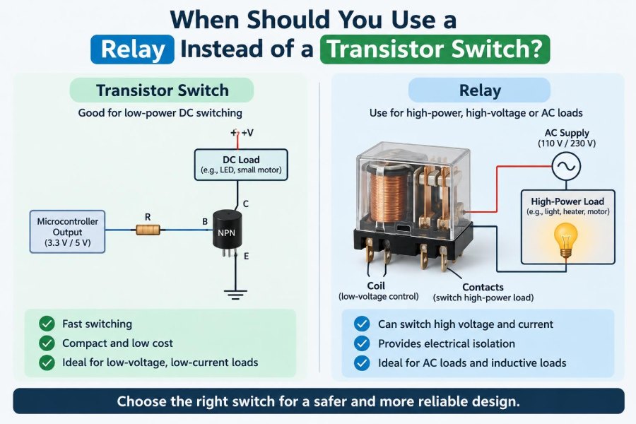
A transistor switch uses a small control signal to regulate a larger current electronically. In low-side switching, a common arrangement, an N-channel MOSFET sits between the load and ground. Driving its gate appropriately allows current to flow.
When fully enhanced, a MOSFET behaves approximately like a low resistance, called RDS(on). A bipolar junction transistor, or BJT, is instead driven into saturation and has a residual voltage drop across it.
Because there are no moving contacts, transistor switches can operate silently and very quickly. They are usually excellent for repeated, low-voltage DC switching.
🧲 What a Relay Does
An electromechanical relay contains a coil, a magnetic armature, and movable contacts. Current through the coil creates a magnetic field, pulling the armature and changing the state of one or more contact sets.
The coil circuit and contact circuit are physically separate. That separation lets a low-voltage controller operate a load whose voltage reference is not shared with the controller, provided the relay’s insulation and ratings are suitable.
A relay contact is a mechanical switch, not a perfect conductor. It has contact resistance, finite switching life, and an arc can form as contacts open under load.
🔍 The Most Important Distinction: Isolation
Use a relay when you need galvanic isolation between the control circuit and the load circuit. Galvanic isolation means there is no intentional conductive electrical path between them. The relay coil transfers command energy magnetically.
This is valuable when a microcontroller must switch an AC line-powered device, a high-voltage battery subsystem, or a circuit with a different and potentially noisy ground. It can reduce ground-loop problems and makes it possible to switch either side of an otherwise independent circuit.
A transistor alone does not provide this separation. An optocoupler, digital isolator, isolated gate driver, or isolated power supply may create isolation around a transistor design, but that is a larger system decision—not an automatic property of the transistor.
🔌 Why Relays Can Switch AC Naturally
A standard MOSFET has an intrinsic body diode and normally conducts current preferentially in one direction when controlled as a simple switch. Switching an AC load therefore requires a circuit designed for bidirectional blocking and conduction, often using back-to-back MOSFETs or a suitable solid-state relay.
Relay contacts do not care about current polarity in the same way. A properly rated relay can open or close many AC circuits directly, including line-powered lamps, fans, and contactors.
That does not mean every relay is safe for every AC circuit. Contact voltage, current, spacing, enclosure design, wiring, fusing, and local electrical requirements remain essential.
🔋 Transistors Usually Win for Low-Voltage DC
For DC loads supplied at 3.3 V, 5 V, 12 V, or 24 V, a MOSFET is often the more efficient and durable choice. Examples include LED strips, DC fans, small pumps, solenoids, battery-powered products, and motor drivers.
A suitable MOSFET can have a voltage drop of only I × RDS(on). Its heat loss is approximately I²R, so a low-resistance device can waste far less energy than a relay coil that must remain energized throughout the on period.
Its electronic operation also avoids contact wear. For a device that switches a DC load many times a day, that difference can dominate the design.
🕒 Switching Speed Changes the Answer
Relays are slow by electronic standards. Their operating and release times are commonly measured in milliseconds, and contact bounce may produce several brief make-and-break events after closure.
A transistor can switch in microseconds or faster when its gate or base is driven properly. That makes it appropriate for pulse-width modulation (PWM), where the switch repeatedly turns on and off to control average motor speed, heater power, or LED brightness.
Do not use an ordinary mechanical relay for PWM. The audible chatter, contact wear, poor timing resolution, and electrical noise make it a poor fit.
🔁 Mechanical Life Versus Contact Life
Relay datasheets often distinguish mechanical life from electrical life. Mechanical life counts operations with little or no contact load. Electrical life accounts for real current, voltage, arcing, and the specific kind of load.
A relay may survive many unloaded movements yet have a much shorter useful life when switching a motor or DC solenoid. DC arcs are especially persistent because, unlike AC, the current does not naturally pass through zero every half cycle.
A transistor has no contacts to erode, but it can still fail from excessive voltage, current, heat, electrostatic discharge, or repeated avalanche stress. “No mechanical wear” does not mean “no design limits.”
🔥 Compare the On-State Power Loss
Every switch dissipates some power while on. For a MOSFET, calculate conduction loss from the expected current and the maximum RDS(on) at the actual gate-drive voltage and temperature—not merely the attractive typical value on page one of a datasheet.
A BJT loss is roughly collector current multiplied by its saturation voltage. This can be acceptable for small loads, but becomes significant at higher currents.
A relay creates two loss paths: coil power and contact resistance. Coil power matters in battery equipment and always-on control panels. At high contact current, contact resistance can also create heat at the terminals.
📈 Inrush Current Is Often the Hidden Constraint
Many loads pull far more current at turn-on than during steady operation. Motors start near stall current, incandescent lamps have low cold filament resistance, and power supplies with large input capacitors can draw a sharp charging surge.
Neither a relay’s headline current rating nor a transistor’s continuous drain-current rating alone proves it will survive. Examine surge capability, safe operating limits, thermal conditions, and load-specific switching ratings.
For example, a relay rated for a resistive load may have a much lower permissible rating for a motor. A MOSFET may tolerate a short pulse only if the pulse energy and junction temperature remain within the datasheet limits.
🌀 Inductive Loads Need a Turn-Off Plan
Motors, relay coils, valves, solenoids, and transformers store energy in magnetic fields. When current is interrupted, that energy tries to keep the current flowing and can produce a damaging voltage spike.
For a DC coil switched by a low-side transistor, a flyback diode across the coil is a common solution. It gives the current a safe recirculation path. Place it physically close to the coil or connector when practical.
The diode slows coil release because current decays gradually. Faster release may require a TVS diode, diode-and-zener arrangement, or another clamp strategy chosen to stay within the transistor’s voltage rating.
⚡ Relay Contacts Also Need Suppression
A common mistake is adding protection only to the transistor that drives a relay coil while ignoring what the relay contacts switch. If the contacts open an inductive load, arcing can rapidly wear or weld them.
Depending on the load and supply, appropriate options include a DC flyback diode, an RC snubber, a metal-oxide varistor (MOV), or a TVS suppressor. The correct component and placement depend on whether the circuit is AC or DC and on the allowed release time.
Suppression reduces stress, but it must be selected deliberately. An incorrectly rated MOV or capacitor can itself become a safety and reliability problem.
🔊 Noise, Bounce, and EMC Matter
Relay coils and contacts can inject interference into nearby electronics. Coil current steps disturb the supply, and contact bounce creates short bursts of switching that may confuse sensitive logic or produce electromagnetic emissions.
Transistor switches avoid contact bounce, but fast voltage and current edges can create their own electromagnetic compatibility, or EMC, challenges. Long wires add inductance and act as antennas.
Use sensible layout: short high-current loops, local decoupling capacitors, controlled return paths, suppression close to the source of the transient, and separation between noisy power wiring and low-level sensor lines.
👂 Silence Is a Functional Requirement Sometimes
A relay makes a click. In an industrial panel, that sound can be useful confirmation of operation. In a bedroom device, laboratory instrument, wearable product, or audio system, it may be unacceptable.
Transistors switch silently. This is a straightforward but genuine reason to choose one, especially where frequent operation would make a relay’s sound conspicuous.
Remember that a transistor-controlled motor can still make audible noise if PWM frequency falls in the hearing range. Silent switching hardware does not automatically create a silent system.
🌡️ Temperature and Thermal Design
Temperature changes both technologies. MOSFET on-resistance generally rises as the device gets hot, increasing dissipation and potentially creating a thermal feedback problem if cooling is inadequate.
Relay coil pickup and release behavior vary with temperature and supply voltage. Contact ratings also assume stated environmental conditions and mounting arrangements.
For a transistor, estimate losses, then use the package thermal resistance, copper area, airflow, and ambient temperature to evaluate junction temperature. For a relay, verify coil voltage range, terminal heating, and derating at elevated temperature.
🧱 Physical Size and Board Layout
For modest DC loads, a transistor and its support components can occupy very little PCB area. This favors compact battery products, dense controllers, and multi-channel boards.
Relays are comparatively bulky because they contain a coil and moving mechanism. Their larger size can be an advantage, however: it can help preserve physical spacing between low-voltage control circuitry and high-voltage contact wiring.
Do not defeat that advantage with careless PCB routing. High-voltage clearance and creepage—the distance through air and along an insulating surface—must be designed for the actual system conditions.
🔄 Relay Contact Forms Offer Useful Flexibility
Relays are convenient when a circuit needs normally open (NO), normally closed (NC), or changeover contacts. A changeover, often called SPDT, can connect a common terminal to one of two paths without building a complementary semiconductor circuit.
An NC contact can support a simple fail-state: when coil power disappears, the contact returns to its resting condition. This can be useful, but never assume it creates a complete safety function without analyzing all failure modes.
Transistor circuits can also provide high-side, low-side, or bidirectional switching, but the design becomes more specialized as the required behavior grows.
🛡️ Fail-Safe Means More Than “Normally Closed”
Mechanical relays are often chosen because their rest state is visually intuitive. Yet a relay can fail with welded contacts, an open coil, stuck mechanics, or degraded insulation. A transistor can fail open or short, depending on the fault and energy involved.
Where a fault could create injury, fire, or major equipment damage, use a system-level safety approach. It may include fuses, thermal cutouts, redundant sensing, contact feedback, interlocks, rated disconnects, and a formal risk assessment.
A single relay or transistor should not be casually treated as a guaranteed safety barrier.
🧠 Control-Circuit Drive Requirements
A microcontroller pin usually cannot drive a relay coil directly. The coil may need tens of milliamperes or more, while the pin has a much lower recommended output current. Use a transistor or MOSFET driver, plus a flyback diode for a DC relay coil.
MOSFET gates draw almost no steady DC current, but they must charge and discharge gate capacitance. At high PWM frequency or with a large MOSFET, a dedicated gate driver may be necessary for fast, cool switching.
Also check logic-level specifications carefully. A MOSFET described as “logic-level” is not automatically low-resistance at 3.3 V; verify RDS(on) at the voltage your controller actually supplies.
🧰 Low-Side and High-Side Switching
Low-side switching is simple because the control device sits near ground. It works well when the load can remain connected to the positive supply while off.
High-side switching disconnects the positive supply instead. It may be required when the load shares a ground with sensors, when a chassis-grounded load must be controlled, or when leaving the load’s positive terminal live would be undesirable.
P-channel MOSFETs can simplify some high-side DC designs, while N-channel MOSFETs often provide lower resistance but need a gate voltage above the source. Relays can switch either side of an isolated contact circuit, subject to safety rules.
💡 Example: Switching an LED Strip
A 12 V LED strip that needs dimming is a clear transistor case. A low-side N-channel MOSFET, selected for suitable voltage margin and low RDS(on) at the available gate voltage, can use PWM for smooth brightness control.
A relay would only provide on/off control, would click at each operation, and cannot be used for normal PWM dimming. It also consumes coil power whenever the strip is on.
If the strip is long, account for wire voltage drop, supply capacity, connector current rating, and heat in the MOSFET. The switch is only one part of the power path.
🚪 Example: Controlling a Mains-Powered Appliance
Suppose a low-voltage controller needs to turn a line-powered ventilation fan on and off. A relay or contactor with contact ratings appropriate to the fan’s voltage, starting behavior, and load category may be a practical solution because it provides physical isolation.
The low-voltage controller still needs a safe relay driver, and the mains side requires correct enclosure, terminals, fuse or protective device selection, conductor sizing, and spacing. These details are not optional extras.
A solid-state solution may also be possible, but it must be designed for the supply type, off-state leakage, heat dissipation, fault behavior, and isolation architecture. Mains work warrants qualified review and applicable local requirements.
🚗 Example: A 12 V Automotive Load
Automotive systems often use relays for high-current loads because the wiring is long, loads are substantial, and relay service practices are familiar. But modern electronic control modules also use protected MOSFET high-side and low-side switches extensively.
A raw transistor design must survive a harsh electrical environment: supply transients, load dump conditions, reverse battery events, inductive wiring, and wide temperature changes. A relay does not automatically solve these problems either; its coil driver and contacts remain exposed to the environment.
For a hobby project, choose components with adequate voltage margin and use load-specific suppression. Do not assume a nominal “12 V” supply stays near 12 V in operation.
📊 A Quick Decision Comparison
| Requirement | Usually favors a relay | Usually favors a transistor switch |
|---|---|---|
| Load type | AC or electrically separate circuits | Low-voltage DC |
| Isolation | Physical coil-to-contact separation needed | Shared ground is acceptable |
| Switching rate | Occasional on/off actions | Frequent switching or PWM |
| Sound | Click is acceptable or useful | Silent operation needed |
| Lifetime limit | Electrical contact life is acceptable | Very high cycle count required |
| Power while on | Coil consumption is acceptable | Low standby and on-state loss matter |
| Switching topology | NO, NC, or changeover contacts help | Dedicated DC high-side/low-side control |
This table is a starting point, not a substitute for checking ratings. A carefully engineered transistor circuit can handle demanding loads, and a properly selected relay remains an excellent choice in many systems.
🚫 Common Mistake: Reading Only the Headline Rating
“10 A relay” and “30 A MOSFET” are incomplete descriptions. The conditions behind a rating matter: DC versus AC, resistive versus inductive load, ambient temperature, heatsinking, switching frequency, voltage, and pulse duration.
Read the datasheet tables, graphs, notes, and package limits. For relays, find the switching rating for your load category. For MOSFETs, inspect RDS(on), maximum drain-source voltage, pulsed limits, thermal data, and safe-operating guidance.
🧪 Prototype Under Realistic Conditions
Bench testing at room temperature with a new component and a short wire is useful, but it may not reveal startup surges, hot enclosures, long-cable ringing, supply dips, or repeated-cycle wear.
Measure voltage at the load and switch during turn-on and turn-off if suitable equipment is available. Check component temperatures after sustained operation. Listen for relay chatter, which can indicate an undervoltage coil supply or unstable control signal.
For high energy or mains-connected hardware, testing should use appropriate protective methods and competent supervision. A prototype is not evidence that an unsafe architecture has become safe.
🧩 Consider the Middle Ground: Solid-State Relays
A solid-state relay, or SSR, uses semiconductor devices rather than moving contacts, often with an optically isolated input. It can offer silent operation, fast switching, and isolation in a convenient module.
Its tradeoffs differ from an electromechanical relay. SSRs can have off-state leakage, on-state voltage drop or resistance, heat generation, and failure modes that may leave the output shorted. AC SSRs and DC SSRs use different internal technologies and are not interchangeable.
An SSR can be the right answer, but it should be evaluated as its own device class rather than assumed to combine every benefit of a relay and a MOSFET without compromise.
✅ A Practical Selection Sequence
- Identify supply voltage, load type, normal current, inrush current, and switching frequency.
- Decide whether galvanic isolation or a default NC/NO contact state is truly required.
- For DC loads, evaluate a MOSFET circuit first when efficiency, silence, PWM, or long cycle life matters.
- For AC loads or separate voltage domains, evaluate a relay, contactor, or appropriately designed SSR.
- Add load suppression, control-side protection, fusing, and thermal design before finalizing the schematic.
- Validate ratings at worst-case voltage, temperature, wiring length, and load behavior.
This sequence prevents a familiar error: selecting a switch first, then trying to force the rest of the circuit to accommodate its limitations.
🏁 The Core Principle: Match the Switch to the System
Use a relay instead of a transistor switch when physical isolation, straightforward AC switching, mechanically defined contact states, or simple switching between independent circuits matters more than speed, silence, efficiency, and extreme cycle life.
Use a transistor switch when the load is low-voltage DC and the design benefits from fast, quiet, efficient, frequent, or PWM-controlled switching. Add isolation externally if the system requires it.
The strongest design decision comes from examining the whole energy path: source, wiring, load, transients, controller, enclosure, and foreseeable faults. The component is never just “a switch.”
Choose a relay for isolation and suitable infrequent power switching; choose a transistor for efficient, fast, repeatable DC control—and verify the real load conditions before trusting either one. 🔌⚙️🛡️