
A pushbutton looks simple: press it and a microcontroller should see a 1; release it and it should see a 0. Yet a circuit built without one small component may report button presses when nobody touched it.
The same mystery appears with unused inputs, open-drain sensor outputs, I²C buses, reset pins, and transistor interfaces. A digital input can appear to work on the bench, then misbehave when a hand approaches, a cable is attached, or another circuit powers down.
The cause is often a floating input: a pin connected to no defined voltage. Pull-up and pull-down resistors give that pin a predictable resting state without preventing another device from changing it.
Once this idea is clear, many recurring digital-circuit problems become easier to design, debug, and prevent.
🧭 The Digital Problem Behind a Simple Wire
Digital systems describe signals as logic low and logic high. In common circuits, low is near ground and high is near the supply voltage, but the receiver does not require exactly 0 V or exactly the supply voltage.
Instead, every input has voltage ranges it recognizes as low, high, or uncertain. A wire that is not deliberately driven can land in that uncertain region, so the circuit has no trustworthy answer to the question, “What logic state is this?”
🌫️ What a Floating Input Really Means
An input floats when nothing provides it with a sufficiently strong path to a defined reference voltage. The pin is electrically connected to the circuit, but its voltage is not intentionally established.
Inputs are usually high impedance, meaning they draw very little current. That is useful because an input does not heavily load the circuit driving it. It also means tiny unwanted currents can move its voltage substantially.
🧲 Why Floating Pins Pick Up Noise
A floating conductor behaves a little like a tiny antenna and capacitor. Electric fields from nearby mains wiring, switching power supplies, motors, radio transmitters, or even a moving hand can couple charge into it.
Leakage currents inside components and across contaminated circuit boards can also influence the pin. The result may be random transitions, repeated interrupts, extra counter increments, or unpredictable power consumption.
🚦 Logic Thresholds Are Not a Single Line
Datasheets specify an input-low maximum and an input-high minimum. Voltages between those limits are typically undefined: the manufacturer does not promise how the input will interpret them.
For a 3.3 V device, for example, a valid high might need to exceed a stated fraction of the supply while a valid low must remain below another limit. Always consult the particular device datasheet; threshold rules vary by logic family and pin type.
⬆️ The Basic Pull-Up Resistor
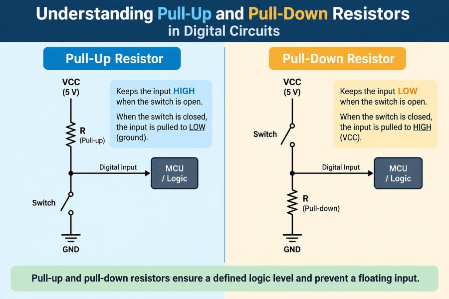
A pull-up resistor connects a signal line to the positive supply rail. When no other circuit actively drives the line, the resistor brings it to logic high.
If a switch or transistor later connects that line to ground, the line becomes low. The resistor limits the current flowing from the supply to ground, making this controlled conflict safe when properly sized.
VCC
 |
[R] pull-up
 |
 +---- input
 |
[switch]
 |
GND
With the switch open, the input reads high. With the switch closed, it reads low.
⬇️ The Basic Pull-Down Resistor
A pull-down resistor connects a signal line to ground. It establishes a logic low whenever another source is not actively driving the line.
A switch can then connect the line to the positive supply rail to create a high state. The arrangement is electrically valid, though pull-ups are often more common in systems that use open-drain outputs.
VCC
 |
[switch]
 |
 +---- input
 |
[R] pull-down
 |
GND
⚖️ Pull-Ups and Pull-Downs Compared
| Feature | Pull-up | Pull-down |
|---|---|---|
| Idle state | Logic high | Logic low |
| Resistor connection | Signal to positive supply | Signal to ground |
| Typical active device | Switch or transistor pulls low | Switch or driver pushes high |
| Common use | Open-drain buses, reset signals, active-low buttons | Default-low enables and switch inputs |
| Current while asserted | Flows through resistor to ground | Flows through resistor from supply |
Neither approach is inherently better. The choice depends on the interface, default-safe state, available output type, power behavior, and firmware convention.
🔘 A Pushbutton Circuit in Practice
A button with a pull-up is a classic arrangement. The input normally reads high, and pressing the button grounds it, producing a low. Software then treats low as “pressed.”
This can feel backward initially, but it has practical advantages. A simple switch provides a reliable ground connection, and many microcontrollers can enable internal pull-ups directly.
🔄 Active-Low Signals Are a Convention, Not an Error
Signals that perform their function at low level are called active-low. Schematics often mark them with a bar, suffix, or naming convention such as RESET_N, depending on the project’s style.
Active-low control lines are common because transistor outputs naturally sink current well, and a pull-up lets multiple compatible devices share certain lines. The crucial practice is clear documentation: firmware and hardware teams must agree on what each level means.
🚪 Open-Drain and Open-Collector Outputs
An open-drain MOSFET output or open-collector bipolar output can pull a line low but cannot actively drive it high. When its transistor is off, the output is effectively disconnected.
A pull-up resistor supplies the missing high state. This arrangement avoids direct contention between devices that might otherwise drive opposite logic levels.
🚌 Why I²C Needs Pull-Up Resistors
I²C uses open-drain or open-collector signaling on its clock and data lines. Devices may pull the bus low, but they release it to allow the external pull-up resistors to restore a high level.
That behavior enables wired-AND operation: if any device holds the line low, the whole bus is low. It supports arbitration and acknowledgment, but resistor selection must account for bus capacitance, speed, supply voltage, and the sink-current capability of connected devices.
🤝 Wired Logic and Shared Lines
Several open-drain outputs can safely share one pulled-up line when the system is designed for that purpose. Any output can assert low; the line becomes high only when all outputs release it.
This is useful for interrupt requests, fault signals, and bus protocols. It is not a license to tie ordinary push-pull outputs together. Two push-pull drivers fighting each other can create excessive current and damaged components.
📏 Choosing a Resistor Value
There is no universal “correct” pull resistor. The value must be low enough to overcome leakage, noise, and the input’s switching requirements, yet high enough to avoid unnecessary current and excessive loading on the device that asserts the signal.
Values in the kilo-ohm range are common for ordinary logic inputs, but that is a starting point rather than a rule. A short, slow button input can tolerate a different choice from a fast bus connected by a cable.
🧮 Estimating Asserted-State Current
When a pull-up is held low, current approximately follows Ohm’s law: I = V / R. A 3.3 V supply with a 10 kΩ pull-up produces about 0.33 mA while a switch or transistor holds the line low.
The corresponding power in the resistor is approximately P = V² / R. For ordinary low-voltage digital pull resistors, this is usually small, but calculate it when voltages are higher or many lines remain asserted for long periods.
⏱️ Rise Time, Capacitance, and Speed
A pull-up raises a signal through resistance, not through a strong active driver. Every trace, cable, connector, and input adds capacitance, and resistance plus capacitance creates an RC time constant.
A larger resistor reduces static current but slows the rising edge. At higher data rates, a line may not reach a valid high before the next sample. This is why I²C pull-up values cannot be chosen solely for low power.
📉 Why Very Large Values Can Fail
A very large resistance saves current, but it creates a weak bias. Leakage current, contamination, capacitively coupled noise, and long cables may pull the voltage away from the intended idle state.
It also slows transitions. A 100 kΩ resistor might be acceptable for a local, slow configuration input, while being unsuitable for a noisy external switch or a fast communication line.
🔥 Why Very Small Values Can Fail
A very small pull resistor creates strong, fast biasing, but it increases current whenever the signal is asserted against the pull. It can exceed what an open-drain device, switch, or low-power source should sink.
It may also make a signal source work harder than intended. The design goal is not the strongest possible pull; it is a defined state with acceptable timing, current, and electrical margins.
🧷 Internal Pull Resistors in Microcontrollers
Many microcontrollers offer configurable internal pull-ups and, on some pins, pull-downs. They reduce external parts and are convenient for buttons, jumpers, and short local connections.
Their resistance is often specified as a broad range rather than a precise value. They may be too weak for high-speed buses, harsh electrical environments, or circuits that must be defined before firmware configures the pin.
🌅 Reset and Power-Up Behavior
At power-up, a microcontroller pin may briefly be an input, a special-function pin, or otherwise not yet controlled by application firmware. If that pin enables power, resets another device, or controls a transistor, its startup state matters.
An external pull resistor can establish the required state from the moment supplies rise. Check the datasheet for internal reset behavior, boot straps, and any pins whose default pulls affect startup mode.
🔋 Multiple Supply Domains Need Care
A pull-up connected to a rail that is powered while the receiving device is off can feed current into that device through input-protection structures. This may cause partial powering, unexpected startup behavior, or operation outside recommended conditions.
Choose the pull rail deliberately. Level shifters, isolation, series resistance, or a pull tied to the correct local supply may be needed when circuits power up and down independently.
🧱 Interfacing Different Logic Voltages
A pull-up defines the high voltage on an open-drain line. Therefore, it also helps determine whether devices at different logic voltages can share that line.
For example, a transistor rated appropriately for the voltage may pull down a line whose resistor goes to another device’s valid logic supply. Do not assume this is safe from a label alone: verify transistor ratings, input thresholds, protection diodes, and unpowered-device behavior.
🌩️ External Wires Are Harder Than PCB Traces
A button on the same board is a very different electrical environment from a switch at the end of a meter-long cable. Cables add capacitance, collect interference, and can carry electrostatic discharge or transient energy into an input.
A pull resistor may still be necessary, but it may not be sufficient. Depending on the environment, use series resistance, filtering, transient protection, shielded wiring, robust grounding, or isolated interfaces.
🎛️ Mechanical Switch Bounce
When a mechanical switch closes or opens, its contacts can bounce for a short time instead of changing state once cleanly. A pull resistor sets the idle state, but it does not automatically eliminate bounce.
Debouncing can be done in software by requiring a stable reading over time, or in hardware with an RC network and a suitable logic input such as a Schmitt trigger. The right method depends on response-time and reliability requirements.
🛡️ Schmitt Triggers Improve Noisy Edges
A Schmitt-trigger input uses different thresholds for rising and falling transitions. This hysteresis prevents a slowly changing or noisy signal from repeatedly switching near one threshold.
It complements pull resistors especially well for long wires, RC debounce circuits, and slowly rising pulled-up signals. Still, hysteresis does not replace proper voltage levels or sensible resistor selection.
🧪 Measuring a Suspect Input
A multimeter may show a plausible average voltage while missing fast glitches. An oscilloscope is much more revealing: observe the line during startup, switching, cable movement, and nearby load activity.
Measure both the idle voltage and the transition shape. Look for slow rise times, ringing, bounce, unexpected pulses, and a level that approaches but does not confidently cross the receiver’s guaranteed threshold.
🧰 A Practical Design Workflow
- Decide what the signal must read when no device is actively asserting it.
- Identify whether the driver is push-pull, open-drain, open-collector, mechanical, or sometimes disconnected.
- Read the receiver’s threshold, leakage, and power-up specifications.
- Estimate pull current and, where speed matters, RC rise time.
- Consider cables, noise sources, supply sequencing, and fault conditions.
- Validate the finished circuit at voltage and temperature extremes relevant to the product.
This process is more dependable than copying a resistor value from an unrelated schematic.
🚫 Common Wiring Mistakes
- Leaving a CMOS input unconnected because it “seems to read low.”
- Adding a pull-up to a line another device actively drives high and low without checking for contention.
- Using an internal pull for a bus that requires controlled rise time.
- Forgetting that a disabled peripheral may release its pin.
- Pulling a signal to a supply rail that is absent or unsafe during part of the power sequence.
- Assuming a pull resistor debounces a switch or protects an external cable.
These errors often create intermittent faults, which are more difficult to diagnose than a circuit that fails consistently.
🗺️ Reading Schematics with Pulls in Mind
Look for resistors from a net to a power symbol or ground symbol, often labeled as pull-up or pull-down in notes. Their purpose may be easy to miss because they are not necessarily near the IC pin they influence.
Also inspect jumpers, test points, connectors, and alternate population options. A resistor marked “DNP” or not fitted may change a line’s default behavior between product variants.
🔍 Troubleshooting an Unstable Digital Signal
Start by asking which component is supposed to drive the line at every moment. If the answer is “nothing” during any state, determine whether a pull resistor is intended and whether it is connected to the correct rail.
Then check resistor value, solder joints, firmware pin configuration, ground continuity, cable routing, and power sequence. Temporarily adding a known external pull can help diagnose a floating condition, but it should not substitute for analyzing the real interface.
✅ The Core Principle to Remember
A digital input needs a defined voltage whenever no active driver is in charge. Pull-up and pull-down resistors provide that default state while allowing switches, transistors, and open-drain outputs to override it.
The best choice is guided by the required idle logic level, output architecture, current budget, timing, noise environment, and startup behavior. A resistor is small, but its role spans logic correctness, reliability, and safe interaction between circuit blocks.
Use a pull resistor to make every inactive digital signal intentionally high or intentionally low—never merely hopeful. That habit prevents a remarkable number of confusing hardware faults. 🔌🧠⚙️