
A prototype boots reliably on the bench, then resets the moment a motor starts. A sensor reading jumps whenever a radio transmits. A digital board passes basic tests but fails after its enclosure is fitted. These are familiar symptoms of a power rail that looks acceptable at first glance but is not behaving acceptably at the point of use.
Power problems are often blamed on “noise,” yet that word can conceal several different mechanisms. A supply may have periodic ripple from its converter, fast switching spikes, a slow voltage sag during a load step, or a ground reference that shifts between two parts of the circuit.
The distinction matters because the fixes are different. Adding a larger capacitor may help a short load transient while doing little for a layout-induced switching spike. Raising the regulator voltage can hide cable loss temporarily while increasing stress elsewhere.
A disciplined diagnosis turns a vague instability into a measurable electrical problem. The goal is not merely to make a waveform look cleaner; it is to ensure every device receives voltage within its required limits, at the frequencies and currents it actually experiences.
⚡ What a Power Rail Really Is
A power rail is the distributed path that delivers a nominal voltage, such as 12 V, 5 V, 3.3 V, or 1.0 V, from its source to loads. It includes more than a regulator output pin: connectors, copper traces, planes, vias, cables, protection parts, filters, and return paths all belong to the rail.
That distributed path has resistance, inductance, and capacitance. Consequently, a rail has different behavior at DC, during a millisecond-scale load change, and during a nanosecond-scale switching edge.
📉 Nominal Voltage Is Not the Whole Specification
A label such as “3.3 V” states the intended operating level, not the complete quality of the supply. Real components specify an allowable voltage range, often with separate requirements for startup, steady operation, transient response, and noise.
A microcontroller may tolerate a broad supply range but still malfunction if its brownout threshold is crossed briefly. An analog reference may remain powered yet introduce conversion error when ripple couples into a measurement path. Always connect a rail measurement to the requirement of the load it serves.
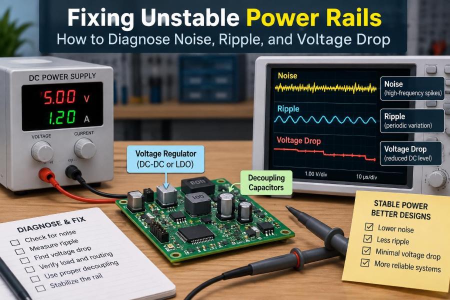
🌊 Separating Ripple, Noise, and Voltage Drop
These terms are related but should not be used interchangeably. Clear language makes troubleshooting much faster.
| Phenomenon | Typical appearance | Common origin | Useful first clue |
|---|---|---|---|
| Voltage drop | Lower average voltage under load | Resistance in cable, connector, trace, or switch | Changes mainly with current |
| Ripple | Regular low- or medium-frequency variation | Rectification, switching converter, inadequate energy storage | Often repeats at a known frequency |
| Noise | Fast spikes, ringing, or broadband disturbance | Switching edges, parasitics, poor layout, EMI coupling | Often aligns with fast events |
| Transient sag | Temporary dip after a load step | Limited control-loop response or local capacitance | Appears when a load turns on |
A single rail can have all four at once. The task is to identify which component is large enough, long enough, or frequent enough to matter.
🔍 Begin With the Symptom, Not the Suspected Fix
Record exactly what fails and when. “The board resets” is a starting point; “the board resets 20 ms after a solenoid is enabled” is much better evidence.
- Does failure occur at power-up, during steady operation, or during a load transition?
- Is it tied to temperature, cable movement, communication activity, or a particular operating mode?
- Do all boards fail, or only units with a certain peripheral attached?
- Is the symptom digital, analog, thermal, or electromagnetic?
This timeline often points to the right rail before an instrument is connected.
🗺️ Map the Complete Power Path
Draw the route from source to load. Include the battery or adapter, fuse, reverse-polarity device, connector, cable, DC/DC converter, linear regulator, distribution copper, and local decoupling capacitors.
Mark where current enters and returns. A schematic shows logical connectivity, but a physical map reveals the distances and shared sections that create voltage drop or ground disturbance. In mixed-signal systems, also identify where noisy loads share impedance with sensitive analog circuitry.
🧮 Use Ohm’s Law for DC Voltage Drop
The first estimate is simple: Vdrop = I × R. If a load draws 2 A through a total path resistance of 0.15 Ω, the drop is 0.3 V. On a nominal 5 V rail, that can be significant.
The total resistance is rarely just the wire. Connector contacts, protection MOSFETs, fuses, narrow traces, via arrays, and solder joints contribute. Resistance also increases with temperature, so a problem may worsen after the system has been operating for a while.
🧷 Never Ignore the Return Path
Current always travels in a loop. Measuring only the positive conductor can obscure the real failure mechanism, because the return conductor or ground plane may be responsible for the apparent supply error.
Shared return impedance produces ground bounce: current from one load creates a voltage across common resistance or inductance, shifting the local ground seen by another circuit. A sensor referenced to that moving ground can report an error even when its positive supply appears stable.
📐 Resistance Explains Sag, Inductance Explains Spikes
Resistance produces a voltage loss proportional to current. Inductance produces a voltage proportional to the rate of current change: V = L × di/dt. Fast current transitions therefore create voltage excursions even in a path with low DC resistance.
A motor driver, switching regulator, or FPGA output bank can change current quickly enough for a short trace, via loop, or capacitor lead to matter. This is why a circuit can measure correctly with a multimeter yet exhibit sharp overshoot on an oscilloscope.
🔋 Understand the Load’s Current Profile
Designers sometimes size a supply using average current only. Average current matters for thermal and continuous ratings, but it is often the peak and edge rate that determine rail stability.
A radio module may draw modest current between transmissions and short high-current bursts during transmit. A motor may draw several times its normal running current at startup or stall. A processor can change demand rapidly as clocks, memory, and peripherals become active.
Obtain a realistic current profile from measurement or component documentation. Then ask whether the source, path, and local storage can supply that profile.
🧰 Choose the Right Measurement Tool
A digital multimeter is excellent for average voltage, continuity, and slow changes. It is not suitable for revealing short dips, ringing, or switching ripple that can disturb high-speed logic.
An oscilloscope is the primary tool for time-domain rail diagnosis. A current probe is especially valuable because it correlates supply voltage events with load current. If one is unavailable, a small current-sense resistor and differential measurement can help, provided its added resistance and bandwidth effects are understood.
🧪 Probe an Oscilloscope Correctly
A poor probing method can create a waveform that belongs mostly to the probe loop. The long ground lead supplied with many passive probes acts as an antenna and adds inductance, which can exaggerate ringing.
For local rail measurements, use a short ground spring or a very short ground connection directly across the capacitor under test. Measure at the load pins or their nearest decoupling capacitor, not only at the regulator output.
Set the probe attenuation, scope bandwidth, and vertical scale deliberately. A bandwidth limit can make a display easier to interpret, but it can also hide fast content; compare limited and full-bandwidth views when needed.
📍 Measure at Source and Load
Two measurement points separate source weakness from distribution weakness. First inspect the supply or regulator output. Then inspect the same rail where the vulnerable IC, motor driver, or sensor actually receives it.
If the source remains stable while the remote load sags, investigate wiring, connectors, trace resistance, and local capacitance. If both locations sag similarly, the converter, upstream source, or total loading is more likely involved.
⏱️ Correlate Voltage With Events
Trigger the oscilloscope on the event that causes trouble: a load-enable signal, motor PWM edge, radio transmit control, reset line, or current-probe threshold. Randomly staring at a rail is much less effective than capturing a repeatable event.
For intermittent faults, use single-shot capture, persistence, segmented memory, or a logic analyzer alongside the scope. The key question is whether the disturbance precedes the failure, follows it, or is merely coincidental.
🔄 Recognize Switch-Mode Converter Ripple
Switch-mode power supplies transfer energy in pulses. Some output ripple at the switching frequency and its harmonics is normal, but its amplitude and shape depend on operating mode, load, inductor current, output capacitor impedance, and control-loop behavior.
A repeating triangular or sawtooth-like component often reflects capacitor charge and discharge. Narrow spikes can arise from switching transitions and measurement layout. Under light load, some converters enter pulse-skipping or burst modes, creating lower-frequency envelope variations that can affect sensitive analog circuits.
🎛️ Distinguish Ripple From Control-Loop Instability
A converter that is stable has a controlled transient response. A poorly compensated or improperly assembled converter can oscillate, often producing pronounced, sustained ringing or low-frequency modulation rather than ordinary switching ripple.
Possible causes include an output capacitor with unsuitable capacitance, ESR, or bias behavior; an incorrect compensation network; excessive layout parasitics; or operating outside the controller’s intended conditions. Do not alter compensation casually: the relevant component datasheet and evaluation layout are the appropriate starting points.
🧱 Capacitors Are Frequency-Dependent Components
Capacitance value alone does not describe decoupling performance. Real capacitors have equivalent series resistance and inductance, commonly abbreviated ESR and ESL. At high frequencies, lead and mounting inductance can dominate.
A bulk capacitor stores energy for slower load changes. Small ceramic capacitors positioned close to IC power pins handle faster local demand. Neither is universally “better”; effective decoupling uses an appropriate combination and a low-inductance connection.
📦 Place Decoupling Where Current Is Needed
A capacitor placed far from an IC cannot fully support a fast transient at that IC because the intervening path has inductance. The capacitor should connect with short, wide paths to the power and ground nodes used by the load.
For a digital IC, follow the manufacturer’s recommended decoupling network and placement guidance. A large capacitor at the board entry is still useful, but it does not replace local capacitors beside fast devices.
🪫 Account for Capacitor Bias and Aging Effects
Some ceramic capacitors lose substantial effective capacitance when DC bias is applied, depending on dielectric type, package size, voltage rating, and temperature. A part marked with a nominal value may provide far less capacitance in its actual circuit condition.
Electrolytic capacitors introduce different tradeoffs, including ESR, lifetime, and temperature sensitivity. Evaluate the effective characteristics relevant to the rail rather than assuming a printed capacitance guarantees a particular transient response.
🔌 Inspect Connectors, Cables, and Protection Parts
Interconnects are common sources of unstable rails, particularly in prototypes and field equipment. A connector can pass a continuity test at negligible current while developing an unacceptable voltage drop under load.
Look for heating, discoloration, loose crimps, worn contacts, undersized conductors, and cable lengths that were not considered in the original design. Also measure across fuses, ideal-diode controllers, reverse-polarity MOSFETs, and current-limit switches while the load is active.
🔥 Treat Thermal Clues as Electrical Evidence
A warm connector, trace, regulator, or protection device often indicates power loss. Since dissipation follows P = I²R, a small unwanted resistance can become conspicuous at higher current.
Thermal cameras can speed up inspection, but a cautious fingertip check on low-voltage equipment or a temperature probe can also reveal a suspect area. Observe electrical safety practices and avoid touching hazardous or mains-connected circuitry.
⚙️ Check Regulator Headroom and Dropout
A linear regulator requires input voltage above its output by some margin. Near that limit, it may no longer regulate properly; the output follows the declining input. The required margin depends on regulator type, current, temperature, and device characteristics.
A buck converter also has practical limits. Duty cycle, switch losses, input dips, and control behavior restrict how closely its output can track input under load. Check minimum input voltage at the converter pins, not just at the power source.
🧯 Respect Current Limits and Startup Behavior
Many regulators and load switches include current limiting, foldback, hiccup protection, or thermal shutdown. These protections can produce a repeating start-stop waveform when a load has excessive inrush, a short circuit, or a startup sequence the supply cannot support.
Observe the input rail, output rail, and load current during startup. A cycling output is not always a defective regulator; it may be correctly responding to an overload or unstable input condition.
🚦 Analyze Inrush Current Separately
Inrush current is the temporary current required to charge input capacitance or start a load. Large capacitor banks, LED drivers, motor controllers, and downstream converters can demand a substantial initial pulse.
If the source or protection circuit cannot deliver that pulse, the rail may collapse before normal operation begins. Possible remedies include controlled soft start, inrush limiting, staged enable timing, a supply with suitable transient capability, or a redesign of the input capacitance and distribution path.
🧲 Keep Noisy Loads From Polluting Sensitive Rails
Motors, relays, solenoids, high-power LEDs, and switching converters produce current changes that can disturb logic and analog rails through shared impedance and electromagnetic coupling. Physical and electrical separation are often more effective than trying to filter everything at the end.
Use separate branches from the source where practical, maintain deliberate return paths, and place local energy storage near pulsed loads. Flyback suppression for inductive loads must be chosen for the switching and release-time requirements; a simple diode is useful in many DC cases but is not a universal solution.
🎚️ Protect Analog and Reference Supplies
Analog front ends are sensitive not only to rail amplitude but also to how noise enters the measurement reference. An ADC measuring a sensor can reject some supply variation if both signal and reference move together, but this depends on the architecture and signal path.
Use filtering, clean reference routing, appropriate grounding, and sensible separation of high-current switching loops from low-level analog nodes. Adding an LDO after a switching regulator can reduce certain noise components, but it adds heat, dropout requirements, and its own stability constraints.
🧭 Avoid Grounding Folklore
“Star ground” and “split ground” are not universal rules. The appropriate return strategy depends on current paths, frequencies, physical layout, and the interfaces between functional blocks.
For fast digital signals, a continuous reference plane often provides a predictable low-inductance return path. Splitting that plane beneath a signal can force return current around a gap and increase noise. Focus on where current flows, rather than applying a ground topology by name alone.
📡 Consider Conducted and Radiated Coupling
A disturbance can reach a rail through conductive paths or through electric and magnetic fields. A long cable may carry common-mode noise, while a high-current loop can magnetically couple into a nearby sensor trace.
If changing wire routing or probe position changes the symptom significantly, coupling is likely part of the problem. Ferrites, common-mode chokes, shielding, filtering, and reduced loop area can help, but each must be selected for the frequency range and impedance involved.
🛠️ Make One Change at a Time
Power debugging becomes confusing when a new capacitor, shorter cable, altered firmware setting, and replacement regulator are introduced together. Improve the system in controlled steps and save before-and-after captures under the same test condition.
This approach identifies causality. It also avoids a fragile “fix” that happens to mask one symptom while causing another, such as converter instability from an unsuitable capacitor change.
🧾 Use a Practical Diagnostic Sequence
- Define the failure and make it repeatable.
- Identify the affected load and its voltage limits.
- Map the source-to-load and return-current paths.
- Measure average voltage and current at source and load.
- Capture rail voltage with correct probing during the triggering event.
- Correlate the event with load current, enable signals, and reset behavior.
- Classify the issue as DC drop, transient sag, ripple, spike, oscillation, or coupling.
- Change the path, source, decoupling, layout, load timing, or filtering appropriate to that mechanism.
- Retest across realistic input voltage, temperature, cable, and load conditions.
This sequence prevents an expensive but common mistake: treating every unstable rail as a capacitor shortage.
🚫 Common Fixes That Miss the Root Cause
Adding bulk capacitance can reduce a slow dip, but it may worsen startup inrush or interact with a regulator. A ferrite bead can isolate high-frequency noise, but it can also create a resonant network with capacitors and cause unexpected impedance peaks.
Likewise, replacing a regulator with a higher-current part will not cure a high-resistance connector, and increasing output voltage is not an acceptable substitute for correcting distribution loss. Each modification should be based on a measured mechanism and verified afterward.
✅ Validate Under Real Operating Conditions
A bench supply with short leads may hide the behavior of a battery, wall adapter, production cable, or shared system supply. Test at the realistic extremes of input voltage and with the actual peripherals operating together.
Check cold start, warm operation, maximum expected load, rapid load cycling, communication bursts, motor stall conditions where safe, and recovery after disturbances. The aim is margin, not a single successful waveform under ideal conditions.
📚 Document the Evidence and the Fix
Save scope screenshots with scale, probe method, trigger source, operating condition, and measurement location. Record component changes and the resulting behavior. This makes reviews easier and helps distinguish a verified correction from a temporary workaround.
Documentation is especially valuable when hardware, firmware, and test teams share responsibility. A reset may be reported as a software issue until a capture shows the rail dipping at exactly the same instant.
🏁 The Core Principle of Stable Power
Stable power delivery is a system property. The regulator, source impedance, distribution network, return path, local capacitors, load current profile, layout, and measurement method all influence the voltage a component truly sees.
The most reliable approach is to measure at the vulnerable load, correlate voltage behavior with current and events, and choose a remedy that addresses the observed mechanism. That turns “power noise” from a catch-all diagnosis into a solvable engineering problem.
A power rail is stable when the real load receives a suitable voltage, with adequate margin, throughout its real operating conditions—not merely when the regulator output looks correct at idle. 🔌📈🛠️