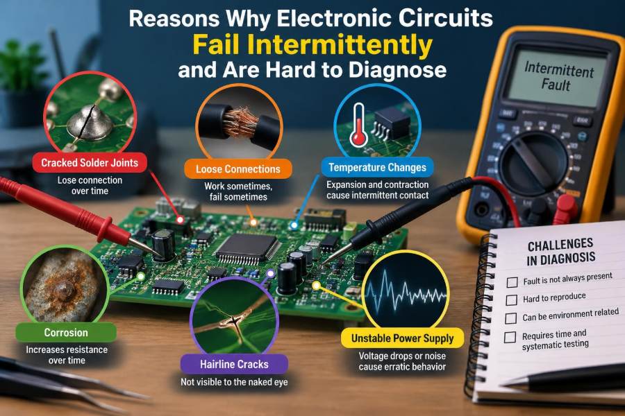

A control board works perfectly on the bench, then fails after it has been installed in a machine. A sensor reports believable values for hours before suddenly dropping out. A device resets only when a motor starts nearby, or only after the enclosure has warmed up.
These faults are among the most frustrating problems in electronics because the circuit can appear healthy during inspection. A technician may power-cycle it, measure the supply rail, reseat a connector, and find that everything has returned to normal.
Intermittent failure is not magic and is rarely random in the strict sense. It is usually a real physical or electrical mechanism that occurs only under a particular combination of temperature, vibration, load, time, humidity, electromagnetic noise, or software state.
Finding it requires more than checking whether a signal exists. The task is to discover which condition changes the circuit from working to failing, then capture evidence before that condition disappears.
🧩 What Makes a Failure Intermittent?
An intermittent fault appears, disappears, or changes behavior without an obvious permanent break. Unlike a shorted diode or visibly burnt resistor, it may leave the circuit operating normally for most of its life.
The trigger can be narrow: a connector moves by a fraction of a millimeter, a semiconductor reaches a particular junction temperature, or a supply dips briefly during a load step. If the trigger is absent during testing, the diagnosis can be misleading.
🔍 Why Normal Bench Tests Often Miss the Problem
Bench testing usually provides stable power, room temperature, little vibration, and easy access to probes. Field equipment experiences cable movement, switching loads, warm enclosures, electrical noise, and sometimes contaminated air.
A circuit that passes a static resistance check or a five-minute functional test has not necessarily been tested under its real operating stresses. The absence of a fault is not proof that the suspected area is healthy.
🌡️ Temperature Changes Electrical Behavior
Temperature affects resistance, leakage current, transistor thresholds, oscillator frequency, battery impedance, and mechanical dimensions. These changes are normally expected within a component’s rating, but marginal designs or damaged parts can cross a functional limit when hot or cold.
For example, a voltage reference may remain within a circuit’s tolerance at room temperature but drift enough in a hot enclosure to make an analog comparator switch at the wrong threshold.
🧊 Thermal Expansion Opens Weak Connections
Different materials expand at different rates. Copper traces, solder, package plastic, circuit-board fiberglass, and connector contacts do not all move together as temperature changes.
A cracked solder joint can make contact while cold and separate when heated. Conversely, contraction can expose a crack at low temperature. This is why carefully controlled warming or cooling can be a powerful diagnostic technique.
🔗 Cracked Solder Joints and Pad Damage
Mechanical stress, repeated thermal cycling, vibration, and poor assembly can create fractures in solder joints. Cracks are common around heavy connectors, relays, large capacitors, power inductors, and components that are frequently handled.
Some fractures are visible under magnification, but many occur beneath packages or at the solder-to-pad interface. A joint can look shiny and intact while its electrical connection changes under stress.
- Inspect stressed joints under strong light and magnification.
- Compare continuity while gently flexing the board, without damaging it.
- Check for lifted pads, fractured vias, and rings around component leads.
🧷 Connector Contacts Are Moving Electrical Parts
Connectors are often treated as passive wiring, yet their contact resistance can change with vibration, oxidation, contamination, insertion force, and cable strain. A low-current digital input may tolerate a poor contact differently from a high-current power connection.
A connector can also fail only when its cable is bent in a particular direction. The useful test is not simply unplugging and reconnecting it; it is observing voltage or signal integrity while applying realistic, gentle movement.
🧪 Oxidation and Surface Contamination
Oxide films, residues, dust, oils, and industrial contaminants can increase contact resistance or create leakage paths. Gold-plated contacts resist oxidation well, but the mating surface, plating wear, and environmental exposure still matter.
Flux residue and moisture can be especially troublesome around high-impedance analog inputs. In such circuits, even a small unwanted surface current can distort a measurement without producing an obvious short circuit.
💧 Humidity Creates Leakage Paths
Water does not have to form visible droplets to affect electronics. Moisture absorbed on a board surface can lower insulation resistance, particularly when ionic residues are present.
The result may be an offset in a sensor amplifier, a false logic level, or slow battery discharge. The symptom can disappear after the board dries, making the original fault difficult to reproduce indoors.
🌫️ Condensation Causes More Than Corrosion
Condensation occurs when a surface falls below the dew point, often after equipment moves between temperatures or when an enclosure cools overnight. A thin film of water can temporarily bridge closely spaced conductors.
Repeated condensation also accelerates corrosion, turning a temporary environmental problem into permanent contact damage. Sealing helps in some products, but enclosure design must also account for pressure changes, heat, and trapped moisture.
⚡ Power Rails Can Look Fine but Still Fail
A multimeter usually reports an average or slowly changing voltage. A digital circuit, however, may reset because of a microsecond-scale dip, ringing event, or transient that the meter never displays.
Power integrity means more than nominal voltage. It includes transient response, ripple, grounding, regulator stability, decoupling placement, and the current path from source to load.
📉 Load Steps Expose Weak Supplies
Motors, solenoids, radios, displays, heaters, and processors can demand sudden current. If the source, cable, fuse holder, connector, regulator, or capacitor has excessive impedance, the rail can sag at the exact moment the load starts.
A typical hypothetical case is a controller that resets only when a relay energizes. The relay coil may not be the direct cause; its current step may expose a weak supply path shared with the controller.
🔋 Aging Capacitors Change Dynamic Performance
Capacitors can lose capacitance, develop higher equivalent series resistance (ESR), or suffer leakage. A circuit may still start and run lightly loaded, yet lose the stored energy and filtering needed during a transient.
Electrolytic capacitors deserve attention in older power supplies, but replacing them blindly is not a complete strategy. Measure ripple and response where possible, and verify polarity, voltage rating, temperature rating, and regulator stability after replacement.
〰️ Ground Is a Network, Not an Ideal Point
Real ground conductors have resistance and inductance. When current flows through a shared return path, one part of the circuit can see a changing ground reference caused by another part’s load.
This common-impedance coupling can make an analog reading jump when a motor runs, or make a digital input appear to change state. A schematic ground symbol does not guarantee that all physical locations are at the same instantaneous voltage.
📡 Electromagnetic Interference Couples into Circuits
Electromagnetic interference, or EMI, enters through cables, board traces, apertures, and power lines. Switching converters, motors, relays, radios, and electrostatic discharge are common sources.
Susceptibility depends on frequency, cable geometry, grounding, shielding, input filtering, and circuit impedance. A design may work on an open bench but fail after long sensor leads turn into effective antennas.
🌀 Inductive Loads Produce Switching Transients
Coils resist a change in current. When current through a relay, solenoid, valve, or motor winding is interrupted, the resulting voltage can rise sharply unless an appropriate suppression path is provided.
A flyback diode is often suitable for a DC coil, though it slows current decay and may not suit every release-time requirement. Other applications use clamps, snubbers, transient suppressors, or driver circuits selected for the switching conditions.
🧠 Logic Timing Margins Can Vanish
Digital circuits depend on timing relationships, voltage thresholds, and setup-and-hold requirements. A timing margin is the amount of room between actual behavior and the boundary at which a device can misread data.
Temperature, supply variation, process variation, long traces, added capacitive load, and clock jitter can consume that margin. The device may run reliably most of the time, then fail only at a particular clock rate or operating temperature.
⏱️ Metastability and Asynchronous Inputs
When an external signal changes close to a clock edge, a flip-flop can enter metastability: a temporary uncertain state before it resolves to a valid logic level. This is a normal physical limitation, not necessarily a defective component.
Asynchronous buttons, sensor pulses, and signals between clock domains need synchronization. A fault may be extremely rare, which makes it look intermittent even though it follows a repeatable probability-based mechanism.
🖲️ Mechanical Switches Bounce
A mechanical switch does not usually change cleanly from open to closed. Its contacts can bounce for a short time, creating multiple transitions instead of one.
If firmware or hardware expects one clean edge, the result can be double counts, unexpected mode changes, or sporadic resets. Debouncing may use timing in software, filtering, Schmitt-trigger inputs, or dedicated circuitry depending on safety and response requirements.
🧮 Firmware State Can Resemble Hardware Failure
Not every intermittent symptom is physical damage. Buffer overruns, race conditions, uninitialized variables, memory corruption, watchdog configuration errors, and rare command sequences can produce behavior that looks like a loose wire.
The strongest clue is often correlation with time, a communication sequence, a specific operating mode, or accumulated activity rather than movement or temperature. Hardware and firmware investigation should proceed together when evidence is ambiguous.
💾 Memory, Configuration, and Brownout Problems
Nonvolatile memory can contain corrupted configuration data, while a brief supply disturbance can cause a processor to execute unpredictably before a proper reset occurs. Brownout detection is designed to hold or reset a controller when supply voltage is too low for reliable operation.
Improper reset sequencing can create failures that depend on startup order. Logging reset causes, supply conditions, and configuration checks can distinguish repeated software startup from a truly dead system.
🔌 Marginal Components May Pass Simple Tests
A diode may pass a meter’s diode test yet leak excessively at operating voltage and temperature. A transistor may switch at low current but fail under its real load. An integrated circuit may have a damaged input that behaves differently only after electrostatic stress.
Component-level tests are useful, but they cannot always recreate in-circuit voltage, current, frequency, thermal, and timing conditions. Compare behavior against a known-good channel or board whenever possible.
🛠️ Previous Repairs Can Introduce New Faults
Hand rework can create solder bridges, overheated pads, damaged traces, poorly seated connectors, or incorrect replacement parts. It can also hide the original clue by temporarily restoring a cracked joint.
Document what has changed before continuing. If a fault began after service, inspect the serviced area first, but do not assume proximity proves causation; a new operating condition may merely have revealed an older weakness.
🧭 Reproduce the Field Conditions Systematically
The fastest route to an intermittent fault is often controlled reproduction. Record when it occurs: warm-up time, input state, power source, load activity, cable position, enclosure state, nearby equipment, and frequency of occurrence.
Change one variable at a time. A useful sequence is to establish a baseline, apply a controlled stress, observe the response, return to baseline, and repeat. Reproducibility transforms a vague complaint into a testable engineering problem.
🧰 Use Instruments That Match the Time Scale
Choose the measurement tool based on what the circuit may be doing. A digital multimeter is excellent for steady voltages and resistance, while an oscilloscope reveals ripple, glitches, ringing, timing, and transient events.
| Suspected behavior | Useful first tool | What to look for |
|---|---|---|
| Slow voltage drift | Multimeter or data logger | Trend versus temperature or time |
| Reset or short glitch | Oscilloscope | Rail dip, reset pulse, ringing |
| Intermittent cable fault | Continuity test plus scope | Change during controlled movement |
| Digital protocol corruption | Logic analyzer or scope | Missing edges, framing, timing errors |
Probe placement matters. A long ground lead on a scope probe can pick up noise and make a clean signal look noisy, so use a short ground spring or appropriate probing method for fast events.
📍 Probe the Right Reference Points
Measurements are meaningful only relative to a reference. If a controller resets, measure its supply directly at the controller’s power pins, not only at the output of a distant regulator.
Also observe related signals: reset line, enable line, load current, communication line, and local ground. Two channels on an oscilloscope can show whether a disturbance occurs before or after the symptom.
🧯 Stress Testing Requires Care
Gentle thermal stimulation, controlled vibration, cable flexing, and load cycling can expose a fault. These methods must stay within safe operating limits and should never compromise isolation barriers, guards, or high-voltage clearances.
Do not use uncontrolled heating, freezing sprays near inappropriate components, or random tapping as a substitute for a plan. Stress is valuable when it tests a hypothesis and is paired with an instrumented observation.
📝 Capture Evidence Instead of Chasing Symptoms
Intermittent faults reward documentation. Record board revision, serial information, environmental conditions, test setup, waveform screenshots, connector positions, component temperatures, and every modification made.
A fault log prevents circular troubleshooting, especially when several people are involved. It also helps separate repeatable triggers from coincidences, such as a failure that happened once while a cable was touched but cannot be repeated.
🚫 Common Diagnostic Shortcuts That Mislead
Reseating every connector, reheating random solder joints, and replacing parts until the symptom disappears can sometimes restore service. However, these actions can erase evidence and leave the underlying mechanism unidentified.
- Do not assume a normal supply reading means the rail has no transient problem.
- Do not trust visual inspection alone for hidden cracks or internal component faults.
- Do not change several variables at once if you need to establish cause.
- Do not mistake temporary recovery for confirmed repair.
✅ Verify the Repair Under Realistic Conditions
A repair is stronger when it survives the stress that originally triggered the failure. If heat caused the symptom, test through a reasonable thermal cycle. If a load startup caused resets, repeat that startup while monitoring the local rail.
Verification should include normal operation as well as the fault-provoking condition. A newly installed component can solve one issue while introducing a polarity error, instability, or inadequate rating elsewhere.
🛡️ Design Practices That Reduce Intermittent Failures
Robust design begins with margin. Use appropriate derating, secure heavy parts, provide strain relief, place decoupling capacitors close to integrated circuits, separate noisy current paths from sensitive signals, and define reset behavior deliberately.
Design for diagnosis too: add accessible test points, useful fault logs, clearly labeled connectors, and provisions to monitor critical rails. These features do not eliminate every failure, but they greatly reduce the time required to understand one.
🧠 The Core Principle: Find the Trigger and the Mechanism
Intermittent circuit failures are difficult because the evidence is conditional. The visible symptom may occur far from its cause: a reset may originate in a connector, a measurement error in board contamination, or a communication fault in an unstable power rail.
The disciplined approach is to identify the triggering condition, measure the relevant electrical behavior at the correct location and time scale, and confirm a physical or logical mechanism. That process is slower than guesswork at first, but it produces repairs that can be trusted.
The key to diagnosing an intermittent electronic failure is to turn a fleeting symptom into a repeatable, measured condition with a defensible cause. 🔌🔍🛠️