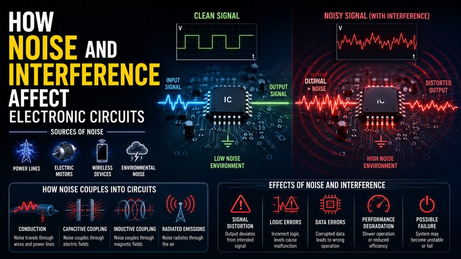

Electronic circuits are designed to carry precise electrical signals, but the real world is electrically noisy. ⚙️📡 A sensor may be trying to measure a few millivolts while a nearby motor is switching several amps. A communication circuit may be receiving a weak radio signal while dozens of digital devices are rapidly turning transistors on and off. Even the wiring inside the same device can allow one signal to disturb another.
These unwanted electrical disturbances are generally described as noise and interference.
Sometimes they produce only a tiny measurement error. In other cases, they can cause audio buzzing, corrupted data, unstable sensors, false switching, communication failures, or even complete circuit malfunction.
Understanding where electrical noise comes from—and how engineers reduce it—is a fundamental part of electronics design. 🔧🧠
🔌 What Is Electrical Noise?
In electronics, noise is any unwanted electrical variation that becomes mixed with a useful signal.
Suppose a temperature sensor is supposed to produce a smooth voltage of:
1.500 volts
If electrical disturbances cause the measured voltage to jump between:
1.492 V, 1.507 V, 1.498 V, and 1.510 V,
then the unwanted fluctuations are noise.
The useful signal is still present, but it has been contaminated.
Noise can appear as:
- Random voltage fluctuations
- Current variations
- High-frequency spikes
- Repetitive hum
- Short electrical pulses
- Radio-frequency signals
- Digital switching disturbances
The effect depends on the sensitivity and design of the circuit.
📡 What Is Electrical Interference?
Interference is closely related to noise, but the term often refers to unwanted energy coming from another identifiable electrical or electromagnetic source.
For example, a nearby electric motor might introduce interference into an audio amplifier.
A mobile phone transmitter might affect poorly shielded electronics.
A high-speed digital clock signal could couple into a neighboring analog circuit.
A useful distinction is:
Noise can be random or internally generated.
Interference often comes from another circuit, device, cable, or electromagnetic source.
In practice, engineers frequently discuss both under the broader subject of electromagnetic compatibility, or EMC.
🎧 A Familiar Example: Hum in an Audio System
One of the easiest examples to understand is the low-pitched hum sometimes heard through speakers.
Electrical power systems operate at low frequencies such as 50 Hz or 60 Hz, depending on the country.
If a small amount of this power-line signal enters an audio circuit, an amplifier may amplify it along with the music.
The result is an audible hum.
Because audio amplifiers can have very high gain, even a tiny unwanted voltage can become noticeable at the speaker.
This demonstrates an important principle:
The smaller the desired signal, the more important noise control becomes.
🔬 Noise Matters Most in Low-Level Signals
Many electronic circuits work with extremely small signals.
Examples include:
- Microphones 🎙️
- Medical sensors ❤️
- Thermocouples 🌡️
- Strain gauges
- Radio receivers 📻
- Photodetectors
- Scientific instruments
- Precision measurement equipment
A microphone may generate only a few millivolts.
A thermocouple may produce even smaller voltage changes.
If an unwanted electrical disturbance is comparable in size to the signal itself, the circuit may struggle to distinguish the real information from the noise.
This is described using the signal-to-noise ratio, or SNR.
📊 What Is Signal-to-Noise Ratio?
Signal-to-noise ratio compares the strength of the desired signal with the strength of unwanted noise.
A high signal-to-noise ratio means:
Strong useful signal + relatively weak noise
A low signal-to-noise ratio means:
Useful signal is close to the noise level
In audio, a high SNR usually produces cleaner sound.
In sensors, it enables more precise measurements.
In communication systems, it makes digital data easier to recover correctly.
Engineers often express SNR in decibels, or dB.
Improving SNR is one of the central goals of low-noise electronics design.
🌡️ Some Noise Is Created by Physics Itself
Not all electronic noise comes from poor wiring or nearby machinery.
Some noise is unavoidable because of the physical behavior of electronic components.
One example is thermal noise.
Atoms and charge carriers inside conductive materials are constantly moving due to thermal energy.
This microscopic motion produces small random voltage fluctuations.
Thermal noise exists even in a perfectly manufactured resistor.
Its magnitude depends on factors including:
- Temperature
- Resistance
- Measurement bandwidth
Cooling certain scientific instruments can reduce thermal noise, which is why highly sensitive detectors may operate at extremely low temperatures. ❄️
⚛️ Shot Noise
Another fundamental form of noise is shot noise.
Electric current consists of discrete charges rather than a perfectly continuous flow.
When electrons or other charge carriers cross certain semiconductor junctions, their arrival has statistical variations.
These variations create tiny fluctuations in current.
Shot noise is especially important in systems handling extremely weak electrical or optical signals.
Examples include:
- Photodiodes
- Semiconductor detectors
- Precision amplifiers
- Optical communication receivers
Like thermal noise, shot noise cannot be completely eliminated because it arises from fundamental physical processes.
🔀 Flicker Noise
Electronic components can also produce flicker noise, often called 1/f noise.
It becomes particularly important at low frequencies.
Semiconductor devices such as transistors can exhibit this type of noise due to microscopic material and charge-carrier effects.
Precision analog designers therefore carefully select components when building circuits that must measure slowly changing signals.
⚡ Switching Circuits Can Be Major Noise Sources
Modern electronics contain huge numbers of transistors that switch rapidly between on and off states.
Every transition changes currents and voltages.
High-speed switching can create unwanted disturbances through:
- Power-supply wiring
- Ground connections
- Nearby circuit traces
- Electromagnetic radiation
Examples of noisy circuits include:
- Switching power supplies
- Microprocessors
- Digital clocks
- Motor controllers
- LED drivers
- High-speed communication interfaces
The faster a signal changes, the more high-frequency energy it can contain.
That high-frequency energy can spread into neighboring circuits.
🧲 Electromagnetic Interference
Changing currents create magnetic fields, while changing voltages create electric fields.
These fields can influence nearby conductors.
This process is one form of electromagnetic interference, commonly abbreviated EMI.
For example, a rapidly switching motor cable can produce electromagnetic fields.
If a sensitive sensor wire runs beside it, unwanted voltage may be induced in the sensor wiring.
The sensor circuit may then interpret this disturbance as genuine information.
This is why cable routing is an important part of industrial and automotive electronics design.
🔗 Capacitive Coupling
Two nearby conductors can behave like a tiny capacitor.
If the voltage on one conductor changes rapidly, some electrical energy can couple into the other conductor through the electric field between them.
This is called capacitive coupling.
Consider two printed-circuit-board traces positioned very close together.
One carries a rapidly changing digital signal.
The other carries a weak analog measurement.
The digital transitions can introduce small disturbances into the analog trace.
Engineers reduce this effect by increasing spacing, changing routing, adding ground structures, or reducing the impedance of sensitive nodes.
🧲 Inductive Coupling
Changing current produces a changing magnetic field.
A nearby wire loop can intercept that changing magnetic field and develop an unwanted voltage.
This is known as inductive coupling.
Large current loops are particularly problematic.
Motors, transformers, relays, and power wiring can produce substantial magnetic fields.
Engineers often reduce inductive coupling by minimizing loop area and keeping sensitive wiring away from high-current conductors.
🌍 Ground Noise and Ground Loops
The word ground sounds as though every ground point should always be at exactly zero volts.
In real circuits, wires and circuit-board traces have resistance and inductance.
When current flows through them, small voltage differences can appear.
This creates ground noise.
A related issue is the ground loop.
A ground loop occurs when circuits are connected to ground through multiple paths, creating a loop in which unwanted current can circulate.
Ground loops are common sources of audio hum and measurement errors.
Engineers avoid them by carefully planning how current returns through a circuit.
🔋 Power Supplies Can Carry Noise
Electronic circuits depend on stable power.
However, power supplies are not perfectly clean.
Switching regulators can produce ripple and high-frequency noise.
Digital circuits can also draw sudden bursts of current, causing temporary voltage changes on the supply lines.
If sensitive analog circuits share the same supply without proper filtering, the disturbances can affect measurements.
Engineers often add decoupling capacitors close to integrated circuits.
These capacitors act as small local energy reservoirs, supplying brief bursts of current while helping reduce high-frequency voltage fluctuations.
🧱 What Is Decoupling?
Decoupling is the process of preventing unwanted electrical activity in one part of a circuit from disturbing another part.
A common technique is placing capacitors between the power and ground pins of integrated circuits.
When a chip suddenly needs extra current, the nearby capacitor can provide some of that current locally.
This reduces rapid disturbances traveling across the entire power distribution system.
Small ceramic capacitors are particularly common for high-frequency decoupling.
Larger capacitors may be used to handle slower variations.
The exact combination depends on the circuit’s frequency range and current requirements.
🔍 Filtering Removes Unwanted Frequencies
Another major noise-control technique is filtering.
A filter allows certain frequencies to pass while reducing others.
📉 Low-Pass Filters
A low-pass filter allows lower-frequency signals through while reducing higher-frequency noise.
It is commonly used with sensors whose output changes slowly.
📈 High-Pass Filters
A high-pass filter reduces low-frequency signals while allowing higher frequencies to pass.
It may be useful when unwanted drift or low-frequency hum needs to be removed.
🎯 Band-Pass Filters
A band-pass filter accepts only a selected range of frequencies.
Radio receivers use carefully designed filters to isolate desired communication channels from surrounding signals.
Filtering works best when the desired signal and unwanted noise occupy different frequency ranges.
🛡️ Shielding Blocks Electromagnetic Interference
Sensitive electronics may be surrounded by conductive material known as shielding.
A metal enclosure can reduce electric-field interference and radio-frequency energy entering or leaving a circuit.
Shielded cables use a conductive layer around the signal wires.
The shield helps intercept unwanted electromagnetic energy before it reaches the signal conductor.
Shielding is common in:
- Audio cables
- Instrumentation
- Radio-frequency systems
- Medical equipment
- Industrial sensors
Effective shielding requires proper mechanical and electrical design.
Simply adding metal does not automatically solve every interference problem.
🔄 Twisted-Pair Wiring Cancels Interference
One clever way to reduce interference is to twist two signal wires together.
This creates a twisted pair.
As the wires alternate positions, external magnetic fields tend to induce similar disturbances in both conductors.
A differential receiver can then reject much of the noise that appears equally on both wires.
Twisted-pair wiring is widely used in:
- Ethernet cables 🌐
- Telephone wiring
- Industrial communication networks
- Automotive electronics
- Sensor systems
It is a simple but highly effective engineering technique.
➕➖ Differential Signaling Rejects Common Noise
A differential signal uses two conductors.
Instead of measuring the voltage of one wire relative to ground, the receiving circuit measures the difference between the two wires.
Suppose noise adds 0.2 volts to both wires.
Because both signals change by approximately the same amount, their difference remains almost unchanged.
This ability to reject shared noise is called common-mode rejection.
Differential signaling is one reason technologies such as Ethernet, USB, CAN bus, and many high-speed communication systems can operate reliably in electrically noisy environments.
🧵 Printed Circuit Board Layout Is Critical
Even if the circuit diagram is correct, poor printed circuit board layout can cause serious noise problems.
Engineers carefully consider:
- Trace length
- Trace spacing
- Ground planes
- Power planes
- Return-current paths
- Connector locations
- Component placement
- High-speed signal routing
A digital clock trace placed beside an analog sensor input might create interference.
A poorly designed current-return path can generate unexpected voltage differences.
Good PCB layout is therefore part of the electrical design—not merely a cosmetic arrangement of components.
⏱️ High-Speed Electronics Behave Differently
At low frequencies, a short wire can often be treated as a simple connection.
At high frequencies, that same wire or circuit trace can behave like a transmission line.
Its geometry begins to influence:
- Impedance
- Reflections
- Crosstalk
- Signal timing
- Electromagnetic radiation
High-speed designers therefore control trace widths, spacing, lengths, and termination.
If signal reflections become severe, a digital waveform may contain ringing or multiple threshold crossings.
A receiver could then misinterpret a single data transition as several transitions.
📣 Crosstalk Between Signals
Crosstalk occurs when a signal on one conductor unintentionally appears on another nearby conductor.
It can result from capacitive or inductive coupling.
In digital electronics, crosstalk may produce brief voltage spikes.
In analog circuits, it may contaminate measurements.
In audio equipment, one channel may faintly appear in another.
Engineers reduce crosstalk using:
- Greater spacing
- Ground planes
- Shorter parallel routing
- Differential signals
- Shielding
- Controlled impedance
As electronic systems become faster and smaller, crosstalk becomes increasingly important.
🚗 Noise in Automotive Electronics
A modern car contains dozens of electronic control units, sensors, motors, communication networks, and power converters.
It is a challenging electrical environment.
Sources of interference can include:
- Ignition systems
- Electric motors
- Alternators
- Fuel injectors
- Switching power converters
- Electric power steering
- High-voltage electric-vehicle systems
Automotive electronics must therefore be designed to resist significant electrical noise.
Communication systems such as CAN bus commonly use differential signaling to improve reliability.
🏭 Industrial Electronics Face Even Harsher Conditions
Factories can contain extremely powerful electrical equipment.
Variable-frequency motor drives, contactors, welders, pumps, large motors, and high-voltage cables can all generate interference.
Meanwhile, sensitive sensors may be measuring:
- Temperature
- Pressure
- Flow
- Position
- Chemical concentration
Industrial engineers use techniques such as:
Shielding → Twisted pairs → Differential signaling → Proper grounding → Filtering → Electrical isolation
to maintain reliable measurements.
Physical cable separation is also important.
Sensitive instrumentation cables are often routed away from high-power motor cables.
⚕️ Medical Electronics Require Extremely Low Noise
Medical equipment illustrates just how important noise control can become.
An electrocardiogram, or ECG, measures tiny electrical signals produced by the heart. ❤️
These biological signals can be much smaller than environmental electrical disturbances.
Designers therefore use:
- High-quality differential amplifiers
- Shielded cables
- Careful grounding
- Filtering
- Isolation
- High common-mode rejection
Without these techniques, power-line interference could overwhelm the signal being measured.
📻 Radio Receivers Are Designed Around Noise
Radio receivers often attempt to detect extraordinarily weak signals.
The antenna captures the desired signal along with atmospheric noise, thermal noise, and transmissions from other sources.
The receiver then uses:
- Low-noise amplifiers
- Filters
- Mixers
- Automatic gain control
- Digital signal processing
to extract useful information.
This demonstrates that electronics often cannot eliminate all noise.
Instead, engineers design systems that can operate successfully despite it.
💻 Digital Circuits Are Not Immune to Noise
Digital signals use discrete states, commonly represented as 0 and 1.
This provides some natural noise tolerance.
For example, a system might interpret voltages near 0 V as logic 0 and higher voltages as logic 1.
A small disturbance may not matter as long as the signal stays within the correct voltage range.
However, sufficiently large noise can push a signal across the decision threshold.
Then the receiver may interpret:
0 as 1
or:
1 as 0
This creates a bit error.
High-speed digital systems therefore still require careful noise control.
✅ Error Detection Provides Another Layer of Protection
Communication systems often add mathematical error-detection methods.
For example, systems may transmit:
- Checksums
- Parity bits
- Cyclic redundancy checks, or CRCs
- Error-correcting codes
The receiver can use this additional information to determine whether data was corrupted.
In some systems, the corrupted information can be retransmitted.
In others, sophisticated coding allows certain errors to be corrected automatically.
This means reliable electronics often use both:
Physical noise reduction + digital error detection
⚡ Transient Spikes Can Be Especially Dangerous
Not all interference is continuous.
Short-duration voltage spikes called transients can occur when equipment switches or electrical energy is suddenly released.
Possible sources include:
- Relays
- Motors
- Inductive loads
- Electrostatic discharge
- Lightning-related disturbances
Although these spikes may last only microseconds or less, they can reach high voltages.
Designers may use protective components such as:
- Surge suppressors
- Clamp devices
- Filters
- Isolation barriers
- Proper grounding
to prevent transients from damaging sensitive electronics.
👆 Electrostatic Discharge
Have you ever touched a metal object after walking across a carpet and felt a small shock?
That is electrostatic discharge, or ESD. ⚡
The voltage involved can be surprisingly high, although the amount of energy is usually small.
Modern integrated circuits contain microscopic structures that can be damaged by ESD.
Electronic products therefore include protection at exposed connections such as:
- USB ports
- Buttons
- Connectors
- Touch interfaces
Manufacturing workers may also use antistatic wrist straps and grounded work surfaces when handling sensitive components.
🧪 Engineers Test Electronics for Interference
Electronic products are commonly tested for both:
Emissions — how much electromagnetic interference the device produces.
Immunity — how well the device continues operating when exposed to interference.
Testing may involve specialized chambers, antennas, signal generators, current-injection equipment, and ESD simulators.
Engineers may intentionally expose a product to electromagnetic energy and observe whether it continues functioning correctly.
This is part of ensuring electromagnetic compatibility.
🔄 EMC: Devices Must Coexist
Electromagnetic compatibility, or EMC, means electronic devices should be able to operate in the same environment without causing unacceptable interference to each other.
A well-designed product should generally:
Avoid producing excessive interference and tolerate reasonable interference from its surroundings.
This is important because modern life is filled with electronics.
Homes, vehicles, factories, airplanes, hospitals, and data centers contain many systems operating close together.
Without EMC engineering, devices could constantly disrupt one another.
🧠 Engineers Use Multiple Defenses at Once
There is rarely one perfect solution to noise.
Instead, engineers use layers of protection.
A sensitive sensor system might use:
Twisted-pair cable → Shielding → Differential amplifier → Input filter → Careful grounding → Digital filtering
Each technique reduces a different pathway through which noise can enter the signal.
This layered strategy is far more reliable than depending on a single filter or shield.
🔍 A Simple Example
Imagine a temperature sensor inside an industrial machine.
The sensor produces a weak voltage signal.
Nearby, a large electric motor repeatedly switches on and off.
Without protection:
Motor switching → Electromagnetic field → Sensor cable → Voltage spike → Incorrect temperature reading
Engineers might improve the system by:
- Moving the sensor cable away from the motor cable.
- Using twisted-pair wiring.
- Adding cable shielding.
- Measuring the signal differentially.
- Filtering high-frequency disturbances.
- Improving grounding.
- Averaging readings digitally.
The temperature measurement then becomes much more stable.
✅ Final Thoughts
Electrical noise and interference are unavoidable parts of real electronic systems. ⚡📡
Some noise comes from fundamental physics, including thermal motion and semiconductor behavior. Other disturbances are created by motors, switching power supplies, radio transmitters, high-speed digital circuits, power wiring, or nearby electrical equipment.
Noise can enter a circuit through conductive connections, electric fields, magnetic fields, shared power supplies, ground paths, or direct electromagnetic radiation.
Its effects range from harmless fluctuations to serious problems such as incorrect sensor readings, audible hum, corrupted communication, false digital switching, and unstable equipment.
Engineers control these problems using a combination of filtering, shielding, decoupling, grounding, twisted-pair wiring, differential signaling, careful PCB layout, physical separation, and error-detection techniques. 🛡️
The central idea is simple: electronic circuits rarely operate in complete electrical isolation.
A successful design must not only perform its intended function—it must also continue performing correctly while surrounded by all the electrical activity of the real world.
That ability to separate useful information from unwanted electrical disturbances is one of the most important foundations of reliable modern electronics. ⚙️🔬📶