
A board that instantly heats up, a bench supply that enters current limit, or a battery that drains in minutes can turn an ordinary repair into a tense troubleshooting session. The obvious suspect is often a short circuit, but finding it is rarely as simple as touching two probes to the board.
Modern PCBs place dense ICs, tiny capacitors, multilayer copper planes, and delicate power-management circuits in a very small area. An aggressive test method can destroy the very component that would have revealed the fault.
The goal is not merely to find a low-resistance path. It is to identify whether that path is actually abnormal, isolate the affected power rail, and apply just enough energy to make the fault visible without overheating surrounding parts.
A disciplined process turns a seemingly mysterious short into a sequence of manageable decisions. It also prevents a common repair mistake: replacing parts based on a meter reading that was normal for the circuit.
⚡ Start by Defining What “Short Circuit” Means
A short circuit is an unintended low-resistance connection between nodes that should be electrically separate. On a PCB, that might mean a supply rail connected to ground, two adjacent signal nets bridged by solder, or an internal fault within a semiconductor.
Not every low resistance is a fault. A processor core supply may legitimately measure only a few ohms to ground because it powers a large number of transistor gates. The key question is whether the reading is consistent with the rail’s design and the board’s symptoms.
🧭 Identify the Symptom Before Reaching for Tools
Observe what happens when power is applied, preferably through a current-limited source. Does the supply immediately limit? Does one region warm up? Does the board consume current only after a button is pressed?
These details separate a permanent input short from a fault that appears only when a regulator enables. A board drawing almost no current may have an open circuit, missing enable signal, or dead controller rather than a short.
🛡️ Make the Board Safe to Test
Disconnect batteries, external adapters, USB cables, and attached modules before resistance or continuity testing. Multiple power sources can backfeed rails and create misleading readings.
Discharge large capacitors where appropriate, using a resistor suited to the circuit rather than momentarily shorting them with a tool. A charged capacitor can damage meter inputs, make probe contact spark, or produce an unstable measurement.
- Work on an ESD-safe surface when handling sensitive boards.
- Remove jewelry and avoid loose conductive objects.
- Use insulated probes with sharp but controlled tips.
- Photograph the board before removing shields, heatsinks, or parts.
🔌 Use a Current-Limited Bench Supply First
A bench supply is one of the safest diagnostic tools because it lets you control voltage and limit fault current. Set the voltage below or equal to the intended rail voltage; never inject an arbitrary high voltage just to make a fault heat up.
Begin with a conservative current limit. Increase it gradually only if the rail and components can tolerate it, while monitoring for temperature rise. Current limiting protects copper traces, small ICs, and connectors from becoming unintended fuses.
📐 Learn the Difference Between Resistance and Continuity
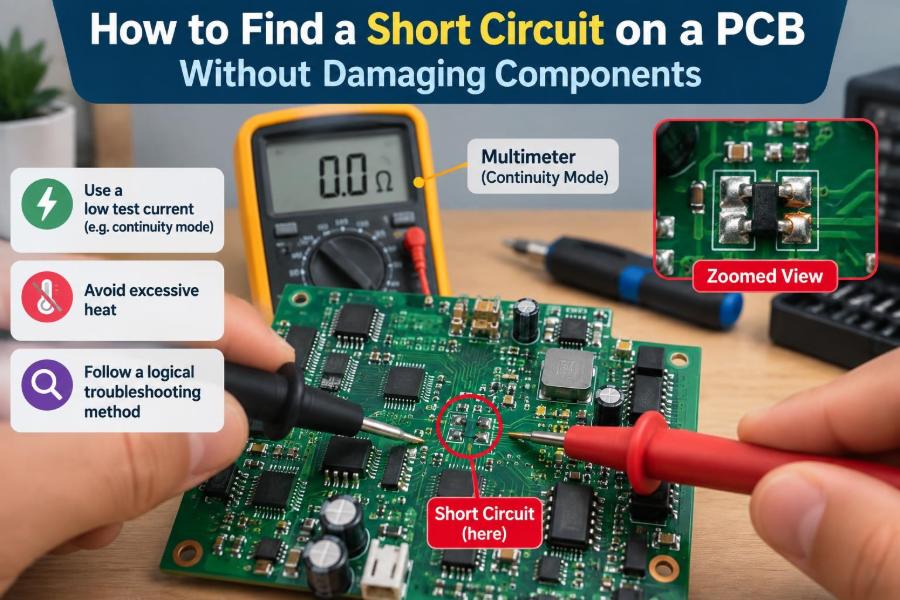
Continuity mode is convenient, but its beep threshold varies by meter. A beep indicates that resistance is below the meter’s internal threshold; it does not prove a dead short.
Resistance mode gives more information, especially when readings are compared with a known-good board or with related rails. Record both probe polarity if the meter behaves differently, since semiconductor junctions can conduct in one direction.
📊 Read Diode Mode as a Comparative Test
Diode mode applies a small test current and displays the resulting voltage drop. Technicians often use it to compare a suspect rail against ground with a known-good board, especially when the board is unpowered.
A very low or zero-like diode reading can suggest a short, but interpretation depends on the circuit. Input protection diodes, MOSFET body diodes, and IC internal structures can all create legitimate readings. Treat diode mode as evidence, not a verdict.
🗺️ Find the Suspect Power Rail
Start at the power input and follow the energy path: connector, fuse or protection device, reverse-polarity stage, input capacitors, switching regulator, and downstream loads. Board markings, schematics, boardview files, and component datasheets make this much faster.
If documentation is unavailable, identify coils, large capacitors, and regulator ICs. A buck converter usually has an inductor between its switching node and output rail; the output side of that inductor is often a useful place to test the regulated supply.
🧱 Remember That Multilayer Boards Hide Connections
Visible traces tell only part of the story. Internal copper planes can connect dozens of capacitors and IC pins, so a short may be electrically widespread while physically tiny.
Do not assume the component nearest the input connector is faulty just because it reads shorted to ground. It may simply be connected to the same plane as the actual failed part elsewhere on the board.
🔍 Inspect Before Injecting Power
Use magnification and strong angled light to inspect connectors, fine-pitch ICs, power MOSFETs, ceramic capacitors, and areas that have experienced liquid exposure or mechanical damage.
Look for solder bridges, metal debris, cracked packages, burnt laminate, green corrosion, displaced shields, and damaged vias. A visible bridge can be corrected before any powered test, avoiding needless stress on the rest of the circuit.
🧼 Clean Contamination Before Drawing Conclusions
Flux residue is usually not a hard short, but moisture, conductive grime, electrolyte residue, and corrosion can create leakage paths that change with humidity or voltage. Surface contamination can also conceal damaged pads and component markings.
Use a suitable electronics cleaner and allow the board to dry fully before retesting. Cleaning is not a substitute for repair, but it removes a variable and makes thermal inspection more reliable.
🔋 Separate the Battery Path from the Main Rail
Battery-powered products often include charging ICs, protection MOSFETs, fuel gauges, and ideal-diode controllers. These devices can couple the battery terminal to system rails in ways that confuse simple resistance measurements.
Disconnect the battery and test the board side independently. Never inject voltage into a battery terminal unless you understand the complete charging and protection path; lithium-ion cells require particular care.
🧩 Check Input Capacitors Early
Multilayer ceramic capacitors are frequent suspects on low-voltage rails because there may be many in parallel and a failed one can become nearly short-circuit. They are inexpensive, small, and often located close to regulators and IC power pins.
However, removing capacitors at random is inefficient and risks lifting pads. First establish which rail is low resistance, then narrow the search by location, thermal response, or segmentation of the rail.
🌡️ Use Heat as a Clue, Not a Weapon
When controlled voltage is injected into a shorted rail, the fault often dissipates more power than the surrounding circuit and becomes warmer. This can reveal a failed capacitor, diode, MOSFET, or IC.
Heat is useful only within safe limits. A tiny short can get hot quickly, while a large copper plane spreads heat and can make the source difficult to locate. Stop if insulation, connectors, or components begin to overheat.
📷 Choose the Right Thermal Viewing Method
A thermal camera is convenient because it displays temperature differences directly. Its limitations include resolution, reflective surfaces, and the fact that a shield or large package may hide the actual source.
Other practical methods can help: a small amount of isopropyl alcohol can evaporate first over a warm spot, and purpose-made thermal-indicating materials can reveal local heating. Use liquids sparingly, keep them away from energized high-voltage areas, and ensure adequate ventilation.
🧊 Interpret a Cold Spot Carefully
Sometimes a component appears cooler than its neighbors because it is connected to a large ground plane or heat sink. That does not clear it of suspicion.
Likewise, the hottest visible part may only be carrying current toward the fault. Trace geometry matters: a narrow copper neck, ferrite bead, or protection component can heat because it has resistance, even when the short is downstream.
🔧 Inject Voltage at the Correct Point
Inject power on the load side of protection circuitry when possible. This avoids unintentionally driving an input charger, USB controller, or reverse-polarity stage in an unintended direction.
For a regulated rail, inject at a decoupling capacitor or the output side of its inductor. Confirm the rail’s nominal voltage from documentation or component markings, then start lower if thermal localization is the only objective.
🚦 Set Voltage and Current Conservatively
Voltage determines which semiconductor junctions may conduct; current limit determines how much heating can occur. Both settings matter. A low-voltage core rail should not receive the voltage intended for a 12 V input rail.
| Situation | Safer initial approach | Why |
|---|---|---|
| Unknown low-voltage logic rail | Use a low starting voltage and modest current limit | Limits stress on IC junctions while checking for heat |
| Known regulator output rail | Stay at or below its rated output voltage | Avoids overvolting downstream loads |
| Main input rail | Verify protection stages and connected subsystems first | Input rails may feed many branches and backfeed paths |
| Battery-connected circuit | Disconnect the cell and map the power path | Prevents unsafe charging or reverse-current conditions |
There is no universal current setting. Start with the least energy likely to reveal useful behavior, and raise it in small steps only when the rail, test point, and components justify it.
✂️ Isolate Branches Instead of Removing Everything
Power rails often split through zero-ohm links, ferrite beads, fuses, inductors, or load switches. These components provide natural boundaries for isolating sections of a circuit.
Measure resistance to ground on each side after lifting or removing a suitable separator. The side that retains the low resistance contains the short. This systematic split-and-test method is usually safer than desoldering every capacitor on a plane.
🧷 Use Inductors to Separate Regulator Outputs
In switching regulators, the inductor often separates the regulator’s switching stage from the output load. Removing or lifting one end can show whether the short lies in the regulator itself or on the rail it supplies.
Label orientation and photograph the area first. Inductors may look symmetrical, but nearby components and exposed pads can be fragile. Reinstalling a part incorrectly or bridging pads can create a new problem.
🧪 Test Semiconductors in Context
MOSFETs, TVS diodes, USB protection arrays, rectifiers, and power-management ICs are common short-circuit candidates. A failed TVS diode across an input can deliberately clamp a transient by becoming low resistance, protecting more expensive circuitry at the cost of itself.
In-circuit measurements can be ambiguous because parallel components affect the reading. If a semiconductor is strongly suspected, isolate it enough to retest before declaring it failed.
🛠️ Treat USB and External Ports as Special Cases
External connectors are exposed to bent contacts, liquid, metal debris, cable faults, and electrostatic events. Inspect every pin for bridges to the shell or adjacent contacts.
Do not assume a short at a USB power pin is inside the main board. Check replaceable daughterboards, cables, port modules, and attached accessories first. Isolation at the connector can prevent unnecessary board-level rework.
💧 Account for Liquid Damage and Corrosion
Liquid damage can produce immediate shorts, delayed corrosion, or intermittent leakage. Corrosion may travel under packages and shields, so a clean-looking top surface does not rule it out.
Inspect affected regions under magnification after cleaning. A repair may require replacing corroded components, rebuilding damaged traces, or removing a shield for access; simply powering the board repeatedly can accelerate electrochemical damage.
🧠 Recognize Normal Low-Resistance Rails
High-current digital rails, such as processor core supplies, can naturally have low resistance because many circuits operate in parallel. Measuring a low value alone is not enough to condemn the board.
Compare with a known-good board of the same revision when available. If that is not possible, examine whether the rail has an actual symptom: excessive current under controlled injection, abnormal heat, or a regulator that cannot start.
🔄 Watch for Backfeeding Paths
Injecting voltage into one rail can power another rail through internal IC protection structures, regulator body diodes, or enabled load switches. This can cause unexpected areas to warm and make the source of the short appear elsewhere.
Use the schematic to identify possible backfeed routes. If documentation is absent, monitor neighboring rails while injecting and reduce voltage if unexpected rail voltages appear.
📏 Measure Voltage Drop Along a Shorted Plane
When a short draws enough controlled current, tiny voltage drops develop along copper paths because copper has finite resistance. A sensitive meter can sometimes detect a higher voltage near the injection point and a lower voltage closer to the fault.
This technique, often called voltage-drop tracing, works best on accessible planes with substantial current flow and stable probe contact. The differences can be very small, so it is not always practical on compact boards or at very low current.
🧰 Remove Components With a Verification Plan
Before desoldering, decide what result will confirm or reject the hypothesis. For example: remove a suspected capacitor, then remeasure rail resistance; or lift a bead, then determine which branch remains shorted.
After each removal, inspect pads for bridges and test again before applying power. Replacing several parts at once may seem faster, but it makes it difficult to learn which action solved the problem and can introduce fresh faults.
🔥 Avoid Common Component-Damaging Mistakes
- Do not bypass a fuse with wire to “see what happens.” A fuse may be limiting damage from a downstream fault.
- Do not use an unregulated adapter as a fault-finding source. It may supply far more current than expected.
- Do not inject above rail voltage to force a thermal signature.
- Do not short probes across a powered rail while searching for readings.
- Do not heat a package indefinitely with hot air when an isolation measurement could first narrow the search.
These shortcuts can turn a repairable board into one with burned traces, damaged ICs, or erased evidence.
📝 Keep a Simple Measurement Log
Record the rail name or location, resistance to ground, diode-mode value, supply voltage, current limit, observed current, and thermal behavior. A few notes prevent circular troubleshooting after several components have been removed.
For complex boards, mark tested branches on a printed image. This is especially useful when multiple rails share the same physical region or when a fault changes after cleaning and rework.
✅ Confirm the Repair Beyond “The Short Is Gone”
After replacing a failed component, verify that resistance and diode readings are plausible, then power the board with current limiting still enabled. Watch the startup current and confirm that each expected rail comes up normally.
Test the function associated with the repaired area: charging, USB data, display startup, radio operation, or load behavior. A short may have been a symptom of a preceding event, so functional testing checks for collateral damage.
🔎 Know When a Short Is Inside an IC
If every external capacitor and branch tests normally but the rail remains shorted, the failed element may be internal to a BGA processor, power-management IC, or multilayer module. Thermal imaging may identify the package, but it cannot always identify the internal die fault.
At that point, replacing the IC may be appropriate only if the part is available, the board has economic value, and you have the tools to perform and verify the rework. Sometimes board replacement is the more reliable engineering decision.
📚 A Repeatable Fault-Finding Sequence
- Disconnect all power sources and visually inspect the board.
- Identify the suspected rail and measure it against ground.
- Determine whether the low reading is plausible for that rail.
- Map protection components, regulators, and branch separators.
- Isolate branches using beads, links, fuses, or inductors.
- Inject controlled power only at a confirmed suitable point.
- Use thermal or voltage-drop clues to localize the fault.
- Remove one justified suspect, then retest.
- Restore power gradually and verify complete operation.
This sequence is adaptable. A simple two-layer hobby board may reveal its fault at visual inspection, while a dense laptop or industrial controller may require documentation, comparison measurements, and careful rail isolation.
🎯 The Core Principle: Control Energy, Then Narrow the Path
Safe short-circuit diagnosis is an exercise in controlled energy and logical isolation. Measurements tell you which net is involved; physical segmentation tells you which area contains the fault; carefully limited injection provides a thermal or voltage clue only when needed.
The most reliable technicians resist the urge to “power it and see.” They build evidence step by step, recognize normal circuit behavior, and avoid putting more electrical stress into a board than the test requires.
Find a PCB short by narrowing the electrical path and applying the minimum controlled energy needed to reveal the fault—not by forcing the board to fail more visibly. With patience, a meter, a current-limited supply, and a clear test plan, many faults become understandable rather than destructive. 🔍⚡🛠️