
A production test station rejects a control board. It will not start, one power rail appears missing, and the technician reaches for the most familiar instrument on the bench: a digital multimeter.
A few resistance checks find no obvious short. Continuity from the input connector to the regulator looks good. Yet, when power is applied, the board still fails exactly as before.
This situation matters because a multimeter is extraordinarily useful, but it does not observe a circuit board in every way a fault can occur. It measures selected electrical quantities at selected points, usually over a limited time interval.
Used with a schematic, a careful procedure, and realistic expectations, it can isolate many failures quickly. Used as the only diagnostic tool, it can also create false confidence. 🔧
🧭 1. The short answer: no
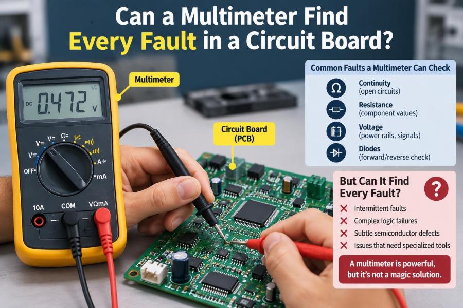
A multimeter cannot find every fault in a circuit board. Some defects only appear at high frequency, under load, at a particular temperature, or during a brief startup sequence.
It also cannot directly see cracked solder joints, corrupted firmware, marginal signal integrity, or incorrect component values unless those problems produce a measurable condition within the meter’s capability.
📏 2. What a multimeter actually measures
A typical digital multimeter measures DC voltage, AC voltage, resistance, current, continuity, and often diode forward voltage. Some models add capacitance, frequency, duty cycle, temperature, or transistor test functions.
These modes are valuable because they translate electrical behavior into numbers. But each number is a measurement made under particular conditions, not a complete description of the circuit.
🔋 3. Voltage measurements answer a specific question
Voltage mode answers: what potential difference exists between these two points now? This makes it ideal for checking power rails, references, battery voltage, logic levels, and regulator outputs.
A correct voltage does not always prove a circuit is healthy. A 3.3 V rail may measure correctly with no load but collapse, ripple, or sequence incorrectly when the system begins operating.
🧱 4. Resistance mode is not a powered-board truth detector
In resistance mode, the meter applies its own small test voltage or current and calculates resistance. The board should normally be unpowered, with stored energy discharged.
Semiconductors, capacitors, parallel paths, and integrated circuits can make an in-circuit resistance reading surprising. A low reading may be normal, while a seemingly reasonable reading may hide a bad connection or a defective device.
🔔 5. Continuity is useful, but easy to overinterpret
Continuity mode is designed to provide a fast audible indication that resistance is below a meter-defined threshold. It is excellent for tracing a broken wire, fuse, switch contact, PCB trace, or connector pin.
It does not prove a path can carry its required current. A corroded connector or cracked joint may beep at the meter’s tiny test current and fail badly when a motor, converter, or processor load draws power.
➡️ 6. Diode mode reveals junction behavior
Diode mode applies a controlled test condition and displays the voltage associated with current through a junction. It is often better than resistance mode for checking ordinary diodes, LEDs, rectifier paths, and some transistor junctions.
Comparing forward and reverse readings can expose a shorted or open diode. In circuit, however, surrounding components can provide alternate paths that alter the result.
🧠 7. The schematic gives the readings meaning
A meter reading alone is rarely a diagnosis. A schematic, block diagram, board view, or known-good comparison tells the technician what voltage, resistance, or diode drop should be expected.
Start by understanding power entry, regulation, reset, clock generation, processor control, and the input or output path related to the symptom. This prevents random probing.
⚡ 8. Power faults are where the meter shines
Many board failures are power-distribution faults, and a multimeter is often the first-choice instrument. It can identify a missing input supply, blown fuse, reverse-polarity protection failure, open trace, or incorrect regulator output.
Useful first checks
- Input voltage at the connector and after protection components
- Voltage on each major rail relative to the intended ground
- Resistance from a suspect rail to ground with power removed
- Voltage across fuses, switches, and current-sense resistors
- Enable, shutdown, and power-good pins where documented
🔥 9. Finding a short circuit takes method
A very low resistance between a supply rail and ground can indicate a shorted capacitor, IC, protection diode, transistor, or solder bridge. It can also be a normal consequence of a low-resistance load on some designs.
First confirm the rail’s expected behavior. Then isolate sections by removing links, opening jumpers, or separating loads when the design permits. Do not inject power blindly into a sensitive rail.
🧯 10. A current-limited supply often beats the meter alone
When a rail is genuinely shorted, a bench supply with carefully set voltage and current limit can reveal where energy is being dissipated. A faulty component may warm relative to the rest of the board.
This approach requires caution: excessive voltage or current can turn a repairable fault into a destroyed IC. The meter helps verify the short; controlled power helps localize its effect.
🧪 11. In-circuit measurements are affected by parallel paths
Components on a board are connected together, so the meter does not necessarily measure only the component touched by the probes. Parallel resistors lower the apparent resistance, capacitor charging changes readings, and IC protection structures can conduct.
If a result is ambiguous, compare with an identical channel, consult the schematic, or lift one component lead when safe and practical. Isolation converts a confusing board-level reading into a meaningful component-level test.
🧩 12. Passive components can still fool you
Resistors may drift upward, capacitors may lose capacitance or gain leakage, inductors may develop intermittent winding faults, and ferrite beads may crack. A basic meter can find some of these faults, but not all.
Capacitance range is especially limited as a diagnostic tool because it may not test at the capacitor’s operating voltage, frequency, bias condition, or ripple current.
🌀 13. ESR and ripple require different tools
An electrolytic or polymer capacitor can show a plausible capacitance value while having excessive equivalent series resistance, often called ESR. That can destabilize a regulator or increase supply ripple.
An oscilloscope is usually the appropriate tool for observing ripple and switching behavior. An ESR meter or LCR meter can provide information a standard multimeter does not.
📈 14. Fast signals disappear into an average
Digital data, clock lines, switching converters, PWM outputs, and transient glitches change far faster than a multimeter display updates. The meter may show an average, an unstable value, or a perfectly unhelpful number.
A line that alternates quickly between 0 V and 3.3 V might be displayed as an intermediate DC voltage. That does not identify the logic state, waveform shape, timing, or data integrity.
🖥️ 15. An oscilloscope answers different questions
An oscilloscope shows voltage versus time. It can reveal ringing, ripple, dropout during startup, missing clocks, reset pulses, overshoot, noisy sensors, and unstable switching regulators.
The multimeter and oscilloscope are complementary. One provides dependable static measurements; the other exposes dynamic behavior that static measurements conceal.
| Question | Most suitable first tool | Why |
|---|---|---|
| Is a rail present? | Multimeter | Accurate DC voltage check |
| Is the rail noisy or collapsing? | Oscilloscope | Shows changes over time |
| Is a rail shorted? | Multimeter, then limited supply | Checks resistance and controlled fault response |
| Is data reaching an IC? | Logic analyzer or oscilloscope | Captures logic timing and activity |
| Is a capacitor degraded? | LCR or ESR meter | Measures relevant component behavior |
⏱️ 16. Intermittent faults are particularly difficult
A board may work on the bench and fail after vibration, handling, warming, or several hours of operation. An intermittent open connection can be electrically invisible during a single continuity test.
Gentle flexing, connector inspection, thermal testing, and monitoring while the fault occurs are often more informative than repeating static measurements.
🌡️ 17. Temperature changes circuit behavior
Some failures are temperature-dependent. A marginal solder joint may open after expansion, an IC may fail only when hot, or a component parameter may drift beyond tolerance in cold conditions.
A multimeter can monitor a rail during thermal stress, but it cannot by itself create, control, or explain the temperature relationship. Thermal imaging, freeze spray, or controlled heating may help when used responsibly.
🔬 18. Visual inspection remains a measurement tool
Before probing, inspect the board under good lighting and magnification. Look for solder bridges, lifted pads, cracked joints, damaged connectors, contamination, overheated areas, missing parts, and incorrect component orientation.
Many physical faults are faster to see than to infer electrically. Clean flux residue or dirt only after documenting suspicious evidence, because cleaning can remove clues.
🪛 19. Connectors and switches deserve suspicion
Faults at connectors, cables, relays, switches, and sockets are common because these parts experience insertion force, vibration, oxidation, and wear. A continuity beep is a starting point, not a load test.
Measure voltage on both sides of the connection while the circuit is operating. A voltage drop across a supposedly closed contact or cable can reveal unwanted resistance.
📉 20. Measure voltage drop under load
Voltage-drop testing is one of the most practical ways to find high-resistance faults. Instead of asking whether a path is continuous, ask how much voltage it loses while carrying current.
For example, compare supply voltage before and after a fuse, connector, trace, or switch while the load is active. An unexpected drop identifies where usable supply voltage is being lost.
🧷 21. Ground is not always one perfect node
Ground symbols on a schematic may represent interconnected conductors with finite resistance and inductance. High current through a return path can create ground offsets that affect sensors, references, communication, and logic thresholds.
A multimeter can measure DC ground differences, but fast ground bounce is better investigated with an oscilloscope and careful probing technique.
🔄 22. Sequencing faults may pass steady-state checks
Modern boards often require supplies, resets, enables, and clocks to appear in a particular order. Once the board reaches a stable state, every rail may look correct even though startup was invalid.
Examples include a regulator that rises too slowly, reset released too early, or one supply arriving before another required rail. These are time-domain faults, not merely voltage-level faults.
🧬 23. Firmware and configuration faults are outside the meter’s view
A microcontroller can have correct power, clock, and reset yet execute corrupted firmware or wait for a missing configuration signal. A multimeter cannot read program memory, decode a bus, or validate software state.
Programming tools, serial logs, debug interfaces, logic analyzers, and known-good firmware are used when the hardware fundamentals are confirmed but behavior remains wrong.
📡 24. Communication problems need protocol-aware testing
I²C, SPI, UART, CAN, Ethernet, USB, and radio interfaces depend on signal levels, timing, termination, protocol rules, and sometimes software configuration. A meter can confirm a supply or static bias, but not a valid transaction.
An oscilloscope can check waveform quality, while a logic analyzer or protocol decoder can show whether meaningful messages are present. For RF circuits, specialized equipment and layout-aware diagnosis are usually essential.
🧷 25. Probe technique can create the apparent fault
Wrong reference points, slipped probes, damaged probe leads, poor contact, incorrect range selection, and an improperly seated current lead can all produce misleading results. Always verify the meter on a known voltage or known resistor when a reading seems impossible.
Be especially careful in current mode. A current meter is placed in series; putting it directly across a voltage source can create a short and damage the meter, the board, or both.
🛡️ 26. Safety and board protection come first
De-energize equipment before resistance, continuity, diode, or component-removal work unless the procedure specifically requires power. Discharge capacitors and observe appropriate precautions around mains circuits, high voltage, batteries, and ESD-sensitive devices.
Use insulated probes, appropriate meter ratings, and a stable work setup. A correct diagnosis is not useful if the measurement process injures someone or introduces a new failure.
🗺️ 27. Build a disciplined fault-finding workflow
A repeatable sequence reduces both time and risk. Begin with the symptom, document what is known, and move from broad checks to focused tests.
- Inspect the board, connectors, and assembly quality.
- Confirm the correct input supply and polarity.
- Check for obvious rail-to-ground shorts with power removed.
- Apply power safely and verify major rails and control signals.
- Test under the condition that produces the failure.
- Compare with a known-good board or identical circuit channel.
- Select a scope, logic analyzer, LCR meter, thermal method, or programmer when the question exceeds meter capability.
✅ 28. The core principle: use the meter to answer bounded questions
A multimeter is not a universal fault detector; it is a precise, portable instrument for answering specific electrical questions. It is exceptionally effective for DC rails, opens, shorts, diode paths, resistance checks, and voltage drops when readings are interpreted in circuit context.
The important skill is recognizing its boundary. When the fault depends on time, frequency, load, temperature, physical stress, firmware, or protocol behavior, choose the tool that can observe that dimension.
A multimeter can find many circuit-board faults, but successful troubleshooting comes from matching the measurement tool to the behavior you need to see. 🔌🧠🛠️