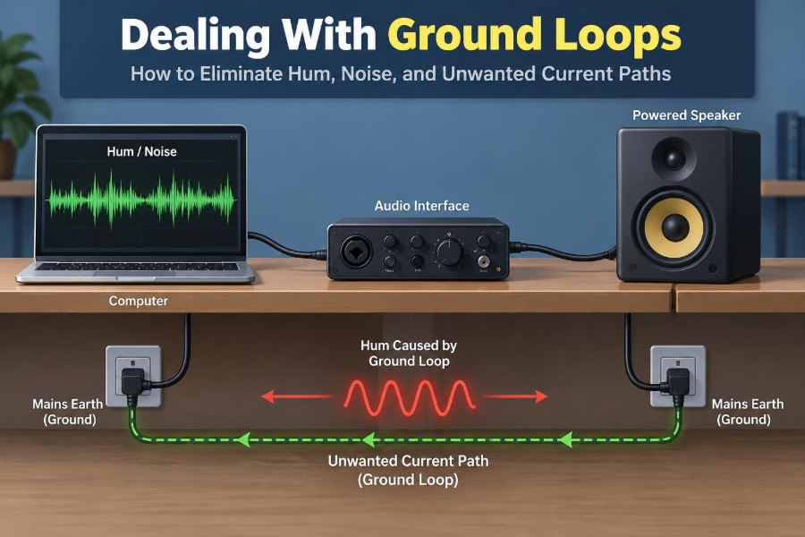

You connect a laptop to a powered speaker, press play, and a low 50/60 Hz hum fills the room. Unplug the charger and the hum disappears. The audio cable was not defective; the system had created an unintended route for current.
Similar problems appear in laboratory benches, industrial control cabinets, RF equipment, CCTV systems, and sensor networks. They can sound like buzz in audio, look like unstable readings on an oscilloscope, or become intermittent communication faults that are difficult to reproduce.
These symptoms are often blamed on “bad grounding,” but that phrase hides the real issue. A ground loop is specifically a closed conductive path that allows unwanted current to circulate between points that were assumed to share the same reference.
Solving it begins by treating grounding as a system design problem rather than a single-wire fix. The right remedy depends on the frequency involved, the equipment class, the signal interface, and—most importantly—electrical safety.
⚡ What a Ground Loop Actually Is
A ground loop exists when two or more ground connections form a closed loop. If there is a voltage difference between grounding points, current can flow around that loop through protective earth conductors, cable shields, signal returns, chassis metal, or a combination of these paths.
The word ground can mean several different things: protective earth for safety, chassis ground for shielding, signal reference for circuit operation, or a connection to local earth. Confusing these roles is one reason ground-loop troubleshooting becomes frustrating.
🧭 The Voltage Difference That Starts the Trouble
No real conductor has zero resistance or zero inductance. When current flows through a ground conductor, a voltage develops across it. Two outlets in the same building, two ends of a long rack, or two cabinets on a factory floor can therefore sit at slightly different potentials.
At mains frequency, this difference may drive a circulating current through cable shields or audio returns. At higher frequencies, even a short wire can develop enough impedance to make two “grounded” points behave very differently.
🔄 Why Closed Paths Matter
A single intentional return path defines where signal or fault current should go. A second path creates a loop, and the current division between paths depends on their resistance, inductance, capacitance, and the frequency of the disturbance.
That is why a system can work perfectly on a bench yet fail after installation. Adding a second cable, rack bond, USB lead, or equipment enclosure may complete a loop that did not previously exist.
🎵 How Hum Enters Audio Systems
Audio equipment is especially sensitive because it handles small signals and often connects units powered from separate mains outlets. A voltage on the shield or audio return can be interpreted as part of the desired signal, producing audible hum or buzz.
Hum at the local mains frequency is common. Strong harmonics can make the sound harsher, and broadband noise may accompany it when switching power supplies, dimmers, or digital equipment inject additional interference.
📏 Common-Mode Noise Versus Ground-Loop Noise
These terms are related but not identical. Common-mode noise appears similarly on both conductors of a signal pair relative to a reference such as earth or chassis. A differential receiver is designed to reject much of it.
A ground loop can create common-mode voltage, but common-mode noise can also arise through capacitive coupling without a direct conductive loop. Identifying the mechanism matters because an isolation transformer, a balanced input, and a better cable route solve different parts of the problem.
🎚️ Why Balanced Connections Help
Balanced interfaces carry a signal on two conductors and use a receiver that responds to their difference. Noise picked up equally by both conductors is largely rejected, provided the source, cable, and receiver are correctly implemented.
Balanced wiring does not eliminate a ground loop by itself. It reduces the conversion of common-mode interference into the wanted signal. A poorly terminated balanced output or an incorrectly wired adapter can remove much of that advantage.
🛡️ Cable Shields Have a Different Job
A shield is primarily an electromagnetic-interference control measure. It provides a low-impedance path for induced currents and can reduce electric-field and RF coupling into the inner conductors.
Whether to connect a shield at one end or both ends depends on frequency, cable type, interface design, and the electromagnetic environment. “Lift the shield at one end” can help some low-frequency analog installations, but it can severely weaken high-frequency shielding.
🏗️ Protective Earth Is Not a Noise-Reduction Wire
Protective earth exists to reduce shock risk by providing a fault-current path and helping exposed conductive parts remain at a safe potential during a fault. It must not be disconnected merely to stop hum.
Using a cheater plug, removing an earth conductor, or defeating a safety bond may appear to solve a noise symptom while creating a hazardous enclosure voltage. Never defeat protective earthing as a ground-loop cure.
🔩 Chassis Ground and Signal Ground
Chassis ground refers to conductive enclosure structures, mounting panels, and metalwork. Signal ground is the circuit’s voltage reference and return network. They may connect at one controlled location, at several locations through a deliberate design, or through capacitive and filtering networks.
The correct arrangement is not universal. A low-frequency precision amplifier and a GHz RF enclosure require very different grounding strategies because the dominant impedances and interference mechanisms differ.
🌐 Earth Ground Is Not Always the Same Potential
People often imagine earth as a perfect zero-volt node. In practice, soil resistance, building wiring, load current, lightning protection arrangements, and conductor length mean different bonded points can have measurable voltage differences.
Within a properly designed electrical installation, protective bonding still serves its safety purpose. The engineering lesson is simply that earth is not an ideal, noise-free reference for precision signals.
🏭 Industrial Systems Add Long-Distance Challenges
Industrial sensor and control cables may run between machines, cabinets, and buildings. Ground potential differences can be much larger than those found between devices on one desk, especially when large motors, welders, or variable-frequency drives share the environment.
For these systems, galvanic isolation and robust differential interfaces are often more reliable than trying to force every remote node to share an identical signal reference.
📡 Digital Links Can Suffer Too
A ground loop is not only an analog-audio problem. Interfaces such as RS-485, CAN, Ethernet through poorly chosen auxiliary connections, USB, and serial ports can encounter excessive common-mode voltage or unwanted return current.
Digital signals may still appear to work until a transient, heavy load, or cable movement pushes the receiver beyond its common-mode range. The result can be retries, corrupted frames, device resets, or damage to interface components.
🔌 The Laptop-and-Display Example
Consider a laptop connected to an external display and powered speakers. The laptop charger, display power cord, HDMI shield, and audio cable can create several reference paths between the devices.
If a hum appears only when the display or charger is connected, that observation narrows the investigation. It does not automatically identify a single bad component; it indicates that the added connection changed the current path or interference coupling.
🧪 Start Troubleshooting by Observing the Symptom
Before changing wiring, describe what the problem does. Does the noise occur only with one source? Does it change with volume control position? Does it remain when the signal input is unplugged? Does it track motor speed, display activity, or mains-connected equipment?
- Hum unchanged by volume may enter after the volume control or through power and grounding paths.
- Noise that changes with computer activity often suggests digital or switching interference.
- A fault that appears only when two distant units connect suggests a potential-difference or common-mode issue.
These observations guide safe tests better than random cable swapping.
🗺️ Draw Every Conductive Connection
Create a simple connection diagram showing power cords, protective-earth bonds, signal cables, shields, coaxial connections, USB leads, mounting hardware, and network equipment. Include connections that seem insignificant.
Then trace every possible route between two chassis or signal references. The loop often becomes obvious on paper: for example, one path through the mains earth and another through a cable shield.
🔍 Isolate One Connection at a Time
With equipment powered down when appropriate, remove or reconnect nonessential signal connections methodically. The goal is to find which added link changes the symptom, not to permanently leave safety connections removed.
Use manufacturer-approved disconnect methods and follow site procedures. In installations with high energy, exposed mains, medical equipment, or critical machinery, troubleshooting should be performed by qualified personnel with suitable test equipment.
📊 Measure Before Declaring a Ground Loop
A digital multimeter can reveal AC or DC voltage between accessible chassis points, but its high input impedance may display voltages caused by small capacitive leakage currents. Such a reading alone does not show how much current can flow.
An oscilloscope, differential probe, current probe, or spectrum analyzer can provide more useful evidence, but each instrument has limitations. A standard earth-referenced oscilloscope probe can itself connect a circuit node to protective earth, so it must be used with care.
⚠️ Oscilloscope Ground Clips Can Create Faults
On many bench oscilloscopes, the probe ground clip is connected to protective earth through the instrument power cord. Clipping it to a non-earth-referenced mains node can cause a short circuit, damaged equipment, or injury.
For floating, high-side, or mains-related measurements, use appropriately rated differential probes, isolated measurement equipment, or a measurement method selected by a trained person. Never assume a small alligator clip is electrically harmless.
🔧 Use Galvanic Isolation Where It Breaks the Path
Galvanic isolation prevents direct conductive current flow while allowing power or information to cross a barrier. Transformers, optocouplers, digital isolators, isolated DC-DC converters, and fiber-optic links are common tools.
An audio isolation transformer can interrupt a low-frequency loop between line-level devices. An isolated RS-485 transceiver can tolerate remote ground differences. The solution works only if the unwanted path is actually interrupted and voltage, bandwidth, and safety ratings are suitable.
🎼 Choosing an Audio Isolation Transformer
For analog audio, select a transformer designed for the intended level and impedance. A device suited to line-level interconnection may distort or load a microphone-level source, while a poorly specified transformer can lose bass, saturate at high level, or introduce phase and frequency-response errors.
Transformer isolation is highly practical, but not invisible. It is a trade-off between breaking DC continuity and preserving the required audio performance.
🔋 Isolated Power Supplies Need Thoughtful Returns
An isolated DC-DC converter creates a separate output domain, but later connections can unintentionally rejoin that domain to the original ground. For example, a USB shield, programming cable, or sensor cable may bridge the isolation barrier.
Check the complete system, including shields and mounting points. Also remember that isolation ratings, creepage distances, and working-voltage limits must match the application rather than being assumed from the converter’s presence alone.
🧱 Star Grounding Helps at Low Frequencies
Star grounding routes multiple low-frequency returns to a shared point, reducing shared-impedance coupling between circuits. It is useful in many audio amplifiers, mixed-signal boards, and power systems where return currents would otherwise pass through sensitive reference conductors.
The “star” need not be a literal geometric star. The key is controlling where currents combine and preventing a noisy return from producing voltage in a quiet circuit’s reference path.
📻 High-Frequency Grounding Follows Different Rules
At RF and fast digital edge rates, wire inductance matters greatly. A long, thin ground wire may have low DC resistance but high impedance to a fast transient. Broad metal planes, short bonds, enclosure seams, and 360-degree cable-shield terminations become more effective.
This is why a grounding method that reduces audio hum can worsen radiated emissions, and why one-end shield termination is not a universal rule. Design for the frequency range of the interference.
🪜 Avoid Shared Return Impedance on Circuit Boards
On a PCB, currents from switching regulators, motors, relays, LEDs, and digital logic can flow through copper shared with analog references. The resulting voltage drop is noise, even though every point is labelled GND in the schematic.
Keep high-current loops compact, route sensitive analog returns away from switching-current paths, and provide continuous reference planes where high-speed signals need them. Good layout prevents many “ground-loop-like” symptoms before cables are attached.
🧲 Route Cables to Reduce Magnetic Pickup
Some interference is induced magnetically rather than conducted through a ground loop. A large loop area formed by separated signal and return wires acts like a pickup loop near transformers, mains cables, and motors.
Twisting a signal pair keeps its conductors close together and reduces loop area. Separating low-level analog cables from power conductors and crossing unavoidable intersections at roughly right angles can also reduce coupling.
🔗 Choose the Interface for the Environment
Single-ended signals reference information to a shared return, making them more vulnerable when devices are far apart or their ground potentials differ. Differential signaling sends information as a voltage difference between two conductors and is generally more tolerant of external disturbance.
For long or noisy runs, choose an interface with appropriate common-mode tolerance, termination requirements, surge protection, and isolation options. A short, convenient consumer cable may be the wrong engineering choice for a factory-floor connection.
🧯 Surge Protection and Ground Loops Are Different Problems
Surge protective devices and bonding conductors are essential parts of many electrical systems, but they do not automatically eliminate signal noise. Conversely, isolation inserted for noise control must not undermine required surge, fault, or shielding practices.
Coordinate the design. A cable entering a building may need bonding and surge protection at the entry point, while the data interface inside may need galvanic isolation to manage normal ground potential differences.
🚫 Common Fixes That Often Backfire
Several tempting remedies may hide symptoms while degrading safety or electromagnetic compatibility:
- Removing protective earth from Class I equipment.
- Using adapters that disconnect earth pins.
- Randomly cutting shields without considering RF performance.
- Connecting every available ground point with long wires.
- Adding ferrites when the root problem is a low-frequency circulating current.
- Assuming a single “ground isolator” works for all signal levels and interfaces.
Ferrite components can reduce high-frequency common-mode noise, but they do not provide DC isolation and usually will not cure a mains-frequency loop current.
🧰 A Practical Remedy Selection Guide
| Observed situation | Likely design direction | Key caution |
|---|---|---|
| Line-level audio hum between powered devices | Balanced interconnection or suitable audio transformer isolation | Confirm level, impedance, and transformer headroom |
| Remote industrial sensor or serial link | Differential interface with galvanic isolation | Verify common-mode, surge, and cable ratings |
| Fast digital or RF interference on cable shields | Low-impedance chassis bonding and proper shield termination | Do not apply low-frequency shield rules blindly |
| Noise within a PCB | Improve return-current layout and power integrity | External grounding changes may not solve it |
The table is a starting point, not a substitute for identifying the actual current path. A remedy should address the mechanism measured or strongly indicated by the evidence.
📝 Document the Final Grounding Scheme
Once a fix works, update the wiring diagram, cable labels, grounding notes, and installation instructions. A solution that depends on one particular shield termination or isolator can be undone during maintenance if it is not documented.
For larger systems, record where chassis bonds occur, which interfaces are isolated, and where shields terminate. This makes later modifications safer and prevents accidental re-creation of a loop.
👷 When to Escalate the Problem
Seek qualified help when the issue involves mains wiring, large installations, medical equipment, hazardous locations, repeated equipment damage, or suspected fault currents. Persistent touch voltage, tripping protective devices, overheating conductors, and damaged connectors are not ordinary audio-noise problems.
Compliance, electrical safety, and electromagnetic compatibility may impose requirements that are not visible from a simple bench test. A quiet system is not necessarily a safe or compliant system.
✅ The Core Principle: Control Every Return Path
Ground-loop control is not about making every conductor disappear into an abstract “ground.” It is about deliberately managing where fault current, signal return current, shield current, and high-frequency interference current are allowed to flow.
Use protective earth for safety, chassis bonds for enclosure and EMI control, signal references for circuit operation, and isolation where direct conductive paths create unacceptable problems. When those functions are designed together, hum and instability become far easier to diagnose and prevent.
The most reliable cure for a ground loop is to identify the complete current path, preserve safety bonding, and then redesign the signal, shield, or isolation path so unwanted current has no harmful route to take. With a clear diagram and measured evidence, even stubborn noise problems become manageable. 🔌🛠️📈