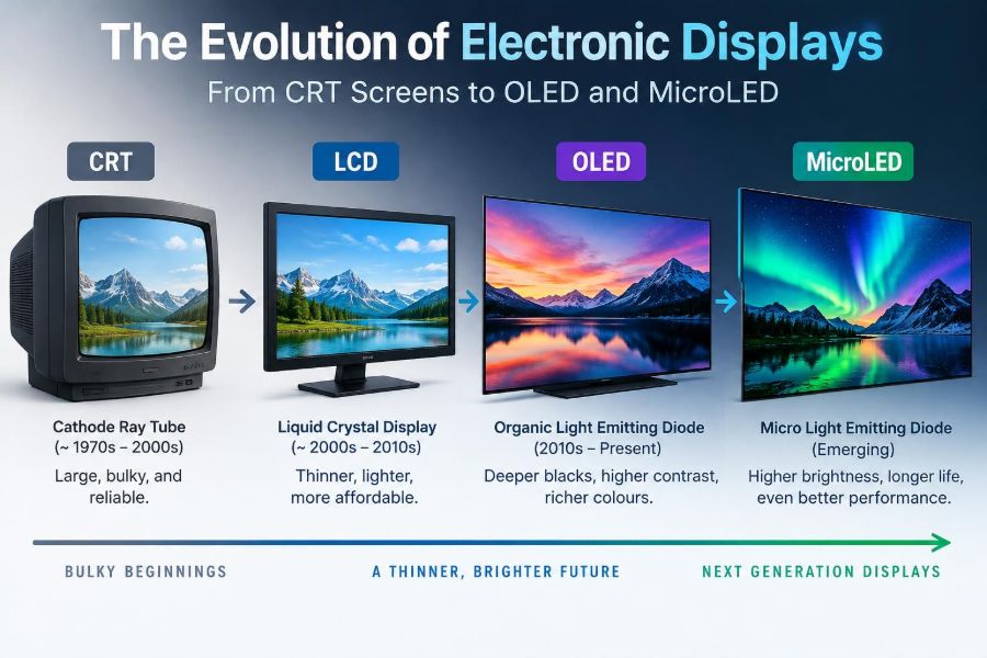

Think about the screens you used this morning: a phone checked before breakfast, a laptop used for work, a dashboard in a car, or a television across the room. They all deliver images through controlled light, but their underlying technologies can be radically different.
A display is more than a sheet of glass with pixels. It is a carefully engineered system that must create light or control it, address millions of picture elements, render color, manage heat, and remain readable under changing conditions.
The change from deep cathode-ray-tube televisions to thin OLED phones did not happen because engineers simply made screens flatter. Each generation solved a specific set of problems while introducing new trade-offs in power, lifetime, manufacturing, cost, and image quality.
Understanding that evolution helps engineers choose the right display for an application—and helps users look past simple labels such as “4K,” “LED,” or “OLED.”
🧩 A Display Is a Light-Control System
At its most basic, a display converts electrical signals into a spatial pattern of visible light. The electronics decide what each pixel should show; the optical stack determines how that decision reaches the viewer’s eyes.
Some displays are emissive: each pixel produces its own light. CRTs, plasma panels, OLEDs, and MicroLEDs belong to this family. Others are transmissive or modulating: they control light from a separate source, as in a conventional LCD with a backlight.
This distinction explains many familiar behaviors. A self-emissive screen can switch a black pixel fully off, while an LCD must block light that is already being produced behind the panel.
📺 The CRT Starting Point
The cathode-ray tube, or CRT, dominated electronic imaging for much of television and computer-display history. Inside a vacuum tube, an electron gun generated and accelerated a narrow beam of electrons toward a phosphor-coated screen.
When the beam struck a phosphor, the material emitted visible light. Magnetic deflection coils swept the beam rapidly across the screen line by line, while the incoming video signal controlled beam intensity.
CRT technology was mature, responsive, and capable of very natural motion. Its defining limitation was physical: making a larger screen required a larger, deeper evacuated glass tube.
🔬 How CRTs Formed Color Images
Color CRTs used three electron beams and repeating red, green, and blue phosphor regions. A perforated metal structure—commonly a shadow mask or aperture grille—helped each beam land on its intended phosphor color.
By varying the intensity of the three beams, the display created a wide range of perceived colors through additive mixing. White, for example, results when red, green, and blue light are produced together at suitable levels.
The arrangement demanded precise alignment. Mechanical shock, nearby magnetic fields, or component aging could disturb convergence, producing colored fringes around objects.
🧲 Why CRTs Were Large and Heavy
A CRT needs distance between the electron gun and the screen so the beam can scan a useful area. The tube must also withstand atmospheric pressure, which calls for thick glass and a robust enclosure.
As screen size increased, depth and mass increased substantially. The high-voltage circuitry, deflection yoke, and heat-generating electronics added further bulk.
These were not merely cosmetic inconveniences. A large CRT affected furniture design, shipping, power consumption, and workplace ergonomics. The desire for thin, wall-mountable screens became a powerful engineering and market driver.
⚡ CRT Strengths and Real Limitations
CRTs had excellent motion behavior because the electron beam could change brightness extremely quickly. They also handled varied input resolutions gracefully, since the image was painted by a scanning beam rather than fixed physical pixels.
But they could flicker at insufficient refresh rates, consume significant power, and require calibration of geometry and color. Their high-voltage operation and vacuum construction also complicated service and end-of-life handling.
- Strengths: fast response, deep blacks in dark conditions, flexible resolution handling.
- Limitations: bulk, weight, geometric distortion, power use, and susceptibility to magnetic interference.
🧪 Flat-Panel Alternatives Arrive
Several flat-panel technologies competed as CRT replacements. Plasma panels used gas discharge cells; liquid-crystal displays controlled backlight transmission; and later organic light-emitting diodes combined thin construction with self-emission.
No technology won simply by having the best picture in every condition. Manufacturing yield, screen size, thickness, operating power, and the needs of portable devices all shaped adoption.
The crucial change was architectural: flat panels addressed an array of pixels electronically instead of steering one beam across a phosphor screen.
🔥 Plasma Displays and Tiny Gas Cells
In a plasma display panel, each subpixel contains a small gas cell. Electrical excitation creates a plasma discharge that produces ultraviolet radiation, which then excites red, green, or blue phosphors.
Like CRTs, plasma displays are emissive. This allowed strong contrast in dark rooms and wide viewing angles, especially compared with many early LCDs.
However, plasma panels generally consumed considerable power, generated heat, and faced practical challenges in fine-pitch, small-screen applications. They became less common as LCD manufacturing improved and OLED entered premium markets.
💡 The LCD Principle: Control, Not Creation
A liquid-crystal display does not normally make the image light by itself. It uses liquid-crystal material to rotate or modulate polarized light from a backlight, then uses color filters to form red, green, and blue subpixels.
The liquid crystals sit between polarizing filters and transparent electrodes. Applying voltage changes molecular orientation, altering how much light can pass through the optical stack.
An LCD pixel is therefore similar to a controllable window placed in front of a lamp. Even a black image requires the panel to block most of the backlight rather than simply turning a pixel off.
🧱 The Layers Inside an LCD
The apparent simplicity of an LCD hides a multilayer optical assembly. Light must be generated evenly, directed toward the viewer, filtered by color, and modulated accurately at each pixel.
| Layer or element | Primary role |
|---|---|
| Backlight | Provides the initial illumination, usually from LEDs. |
| Polarizers | Establish and analyze light polarization for liquid-crystal control. |
| TFT array | Applies controlled voltage to individual subpixels. |
| Liquid-crystal layer | Modulates transmitted light. |
| Color filter | Creates red, green, and blue subpixel output. |
Losses occur at several layers. This is one reason LCD efficiency depends heavily on backlight design and why increasing brightness can increase energy use.
🧷 Active-Matrix Addressing
Modern LCDs and OLED displays commonly use an active matrix. Each subpixel has thin-film transistors, or TFTs, that act as tiny switches and, depending on the design, help hold the desired drive level between updates.
Without active-matrix control, a large array would suffer from slow response, unwanted interactions between pixels, and poor contrast. Active-matrix addressing made high-resolution flat displays practical.
The display controller sends pixel data in rows and columns. This requires careful timing, uniform electrical behavior, and compensation for variations across the panel.
🌈 LCD Panel Modes Matter
The type of liquid-crystal alignment strongly affects viewing angle, contrast, response time, and cost. The familiar labels IPS, VA, and TN describe different families of LCD behavior rather than universal quality rankings.
Common LCD trade-offs
- TN: often enables fast pixel transitions, but historically has narrower viewing angles and weaker color stability.
- IPS: is widely valued for stable color and broad viewing angles, useful for monitors and mobile devices.
- VA: can provide stronger native contrast than many IPS designs, but transition behavior can vary by panel.
Specific implementations matter more than a label alone. A well-designed panel can outperform a weaker panel from another mode in the use case that matters to the buyer.
🔦 LED LCD Is Still LCD
“LED TV” usually means an LCD television illuminated by light-emitting diodes instead of older fluorescent lamps. The LCD layer still performs the image modulation.
LED backlights enabled thinner products, improved efficiency, and more flexible illumination layouts. Edge-lit designs place LEDs around the perimeter; direct-lit designs place them behind the panel.
The terminology can confuse consumers because OLED and MicroLED are also LED-related names. The key question is whether LEDs form only the backlight or whether they are the image-forming pixels themselves.
⬛ Local Dimming and LCD Contrast
Local dimming divides an LCD backlight into independently controlled zones. A dark area of a scene can receive less backlight while a bright object receives more, improving perceived contrast.
Because one zone may cover many pixels, local dimming cannot match pixel-level light control. A bright subtitle against a dark scene can illuminate a surrounding area, producing a visible halo or blooming effect.
More and smaller zones generally improve control, but add driver complexity, heat, cost, and algorithmic demands. Backlight control must anticipate image content quickly enough to avoid distracting changes.
🔵 Quantum Dots Improve Backlights
Quantum dots are nanoscale semiconductor particles whose emitted color depends partly on particle size and material properties. In many displays, they convert light from a blue LED source into highly saturated red and green components.
This helps an LCD produce a wider color gamut while retaining a relatively efficient backlight. Quantum-dot enhancement is an optical improvement, not a replacement for the LCD switching layer.
The phrase “QLED” is commonly used for quantum-dot LCD products, though naming conventions vary. It should not be assumed to mean that every pixel is self-emissive.
📱 Why OLED Changed Portable Screens
An OLED, or organic light-emitting diode, uses organic semiconductor layers that emit light when current flows through them. Each subpixel is an emitter, so no separate backlight is required.
This structure supports very thin panels, high contrast, and the ability to illuminate only the pixels needed by the image. A dark user interface can reduce display power in situations where many OLED pixels remain off or dim.
Power behavior is content-dependent. A mostly white screen at high brightness can require substantial power because many subpixels are actively producing light.
🎨 OLED Color and Pixel Architectures
OLED displays use different arrangements to produce color. Some use red, green, and blue emissive subpixels directly. Others use a broad-spectrum OLED emitter with color filters, sometimes supplemented by an unfiltered white subpixel.
These choices affect brightness, color purity, pixel geometry, lifetime management, and manufacturing strategy. Pixel layouts are often less obvious than their marketing description suggests.
For engineers, the useful lesson is that resolution alone does not fully describe rendered detail. Subpixel arrangement, rendering algorithms, and optical effects can influence text sharpness and fine-line appearance.
🖤 True Blacks and Per-Pixel Control
When an OLED pixel is commanded to black, it can be electrically turned off. In a dark room, this allows the screen to avoid the residual glow associated with light leaking through an LCD.
Per-pixel control also helps with small bright objects on dark backgrounds: a star field, a white cursor, or subtitles need not brighten a broad backlight zone.
Contrast still depends on viewing conditions. Reflections from the screen surface and ambient room light can wash out perceived black levels on any display technology.
⏱️ Response Time, Refresh Rate, and Motion
Response time describes how quickly a pixel changes state. Refresh rate describes how often the display receives or presents a new frame. They are related to motion quality but are not the same specification.
Slow pixel transitions can create ghosting, while low refresh rate can make motion appear less continuous. Sample-and-hold behavior, where each frame remains visible until the next one, can also cause perceived blur during eye tracking even when pixel transitions are fast.
Gaming displays may use higher refresh rates, variable refresh mechanisms, backlight strobing, or motion processing. Each approach has trade-offs involving brightness, artifacts, latency, and viewer comfort.
⚠️ OLED Aging and Image Retention
OLED emitters gradually change with use, and red, green, and blue materials may age at different rates. Persistent bright static elements—such as logos, control panels, or status bars—can create unequal wear over long periods.
Temporary image retention is not always permanent burn-in. A faint remnant may disappear after normal varied use, whereas permanent differential aging remains visible because some pixels have physically changed more than others.
Manufacturers use measures such as pixel shifting, brightness management, compensation cycles, and static-image detection. These reduce risk but do not make all usage patterns equivalent.
🌞 Brightness, Reflections, and HDR
High dynamic range, or HDR, aims to reproduce a larger range between dark and bright image areas, often alongside wider color reproduction. A convincing HDR result requires more than a high peak-brightness number.
The display must control bright highlights without destroying nearby shadow detail. Its tone-mapping behavior, black level, color volume, ambient light, and source mastering all contribute to the outcome.
In a bright office or outdoors, anti-reflective coatings and sustained full-screen brightness can matter more than perfect black levels. Selecting a display always begins with its actual environment.
🔌 Power Consumption Depends on Content
LCD power is strongly influenced by the backlight, which may remain relatively active even for dark images. Local dimming can reduce backlight output in dark scenes, but its control is limited by zone size.
OLED power varies more directly with displayed content. Bright white documents, spreadsheets, and web pages can be demanding; dark themes and sparse imagery may require less energy at the same apparent setting.
Brightness settings dominate many real-world comparisons. It is misleading to describe one technology as universally lower power without specifying panel size, brightness, image content, refresh rate, and backlight or pixel-driving design.
🧊 Flexible and Foldable OLED Panels
OLED layers can be fabricated on flexible substrates, enabling curved, bendable, and foldable display assemblies. The emitting film itself is only one part of the system; the cover layer, touch sensor, encapsulation, adhesives, and hinge mechanics are equally significant.
Flexible products must manage strain at the fold, prevent moisture ingress, and maintain an acceptable surface feel. Organic materials are particularly sensitive to moisture and oxygen, making encapsulation critical.
A flexible panel does not automatically mean a durable device. Reliability depends on the complete mechanical and environmental design.
🧬 What Makes MicroLED Different
MicroLED uses microscopic inorganic LEDs as individual display emitters. Like OLED, it is self-emissive and can provide pixel-level control. Unlike OLED, its light-emitting material is inorganic rather than organic.
The technology is attractive because inorganic LEDs can offer high brightness, strong efficiency potential, and good resistance to some aging mechanisms associated with organic emitters. These properties are promising, not a guarantee that every MicroLED product will lead every metric.
Its central challenge is manufacturing: a large display contains an enormous number of tiny red, green, and blue emitters that must be placed, connected, tested, and repaired reliably.
🏭 The Manufacturing Challenge of Mass Transfer
Moving vast numbers of microscopic LED chips from their growth wafer to a display backplane is called mass transfer. Each emitter must be accurately positioned and electrically connected without damaging neighboring devices.
A single defective subpixel can be noticeable, so production needs inspection and repair processes. Yield—the fraction of manufactured panels that meet requirements—has a major effect on cost.
This is why an elegant device-level concept can take years to become widely available. Display innovation is as much a manufacturing problem as a materials-science problem.
🟢 Color Conversion and MicroLED Design Choices
One MicroLED approach transfers separate red, green, and blue emitters. Another may use one emitter color, often blue, with color-conversion materials to create other colors.
Separate-color approaches face alignment and transfer challenges for multiple materials. Color conversion can simplify some transfer steps but introduces its own questions about conversion efficiency, uniformity, and long-term stability.
There is no single universally best architecture. The optimum depends on pixel size, target brightness, manufacturing equipment, intended product size, and acceptable cost.
📏 Pixel Pitch and Viewing Distance
Pixel pitch is the center-to-center spacing between adjacent pixels. It is particularly important for large direct-view LED walls, where the viewer may be close enough to see the pixel structure.
A very large display can look seamless from across a room yet coarse from a few steps away. Conversely, a fine-pitch display can be excessive if it will only be viewed at long distance.
Resolution should therefore be evaluated with physical screen size and viewing distance, not as an isolated number. This principle applies to televisions, monitors, digital signage, and MicroLED video walls.
🖥️ Choosing Technology by Application
There is no display technology that is best in every setting. The correct choice follows the visual task, content pattern, environment, budget, maintenance plan, and required lifetime.
- Office monitor: prioritize text clarity, ergonomics, reflections, and sustained use behavior.
- Dark-room cinema: contrast control and shadow detail become especially visible.
- Mobile device: thinness, power behavior, outdoor readability, and touch integration matter.
- Control room or signage: reliability, static-content handling, serviceability, and viewing distance may dominate.
A specification sheet is useful, but a deployment requirement is more useful. “Readable under reflected daylight for long shifts” is a better design target than simply “high brightness.”
🛠️ Practical Habits for Better Display Use
Users can improve both comfort and display longevity with simple decisions. Set brightness for the room rather than permanently using the maximum setting, and position screens to reduce direct reflections.
For OLED devices that display static dashboards for long hours, use screen savers, automatic sleep, and interface layouts that avoid a few bright fixed elements when practical. These precautions manage cumulative stress; they are not reasons to avoid OLED altogether.
For color-critical work, allow a display to warm up, use appropriate color settings, and calibrate when the workflow justifies it. A vivid factory mode is not necessarily an accurate one.
🔍 Common Specification Mistakes
One common mistake is treating contrast ratio, peak brightness, resolution, or refresh rate as a complete measure of quality. Manufacturers may measure these under different conditions, and one impressive figure can conceal a compromise elsewhere.
Another is confusing “LED” with a self-emissive LED-pixel display. Ask whether the product is an LCD with LED backlighting, an OLED panel, or a direct-view MicroLED system.
Finally, do not judge a display only in a dark showroom. Check text, motion, viewing angle, reflections, dim scenes, and the type of content you actually use.
♻️ Repairability and End-of-Life Questions
Display systems combine glass, adhesives, metals, semiconductors, polarizers, and sometimes complex coatings. Their thin integrated construction can make repair difficult even when only one component has failed.
Design choices such as modular power boards, replaceable backlights, accessible connectors, and repairable enclosures can extend useful product life. Large LED installations often benefit from serviceable modules, although module seams and calibration add design considerations.
Energy efficiency matters, but durability and repairability matter too. Replacing a functioning device prematurely can offset some of the benefit gained from a more efficient panel.
🚀 Where Display Engineering Is Heading
Future progress is likely to come from several directions at once: improved emitters, better backplanes, more efficient optical films, smarter drive algorithms, and manufacturing methods that raise yield.
Researchers and product engineers are also exploring transparent displays, augmented-reality optics, higher-density MicroLED arrays, and novel color-conversion approaches. Not every laboratory demonstration becomes a mass-market product, because scale, cost, reliability, and repairability remain decisive.
The long-term trend is toward more localized control of light—first by zones, then by pixels, and increasingly by carefully engineered subpixel structures.
🧠 The Core Lesson: Match Light Control to the Job
The journey from CRT to LCD, OLED, and MicroLED is a story of increasingly precise light control. CRTs scanned phosphors with electron beams; LCDs modulate a shared backlight; OLED and MicroLED place light generation at or near the pixel itself.
Each step improves some combination of thickness, contrast, color, power behavior, or design flexibility, while creating new engineering constraints. LCD remains highly capable and widely useful. OLED offers compelling per-pixel control but requires aging management. MicroLED offers major promise while facing formidable production challenges.
The most useful question is not “Which display is best?” but “Which technology best controls light, power, and reliability for this specific viewing task?”
Electronic displays will keep changing, but the engineering logic remains clear: image quality comes from materials, electronics, optics, manufacturing, and human viewing conditions working together—not from a label on the box. 🔌🖥️✨