
A phone that will not charge, a dim LED strip, and a car battery that struggles on a cold morning can look like unrelated problems. Yet each one can be understood by asking the same questions: What voltage is available? How much current is flowing? What is limiting that current?
These three quantities are the vocabulary of almost every electrical circuit. They explain why a resistor gets warm, why a wire can overheat, why a battery voltage drops under load, and why an electronic device may behave perfectly on a bench supply but fail in a real installation.
The familiar water-pipe analogy can help at first, but practical circuits demand a little more precision. Voltage is not “electricity,” current is not automatically dangerous at every value, and resistance is not merely an obstacle added to make equations harder.
Once the relationship among voltage, current, and resistance becomes intuitive, circuit diagrams become less abstract. Troubleshooting also becomes more systematic: measure, compare, calculate, and identify where the expected electrical behavior changes.
⚡ The Three Quantities Behind Every Circuit
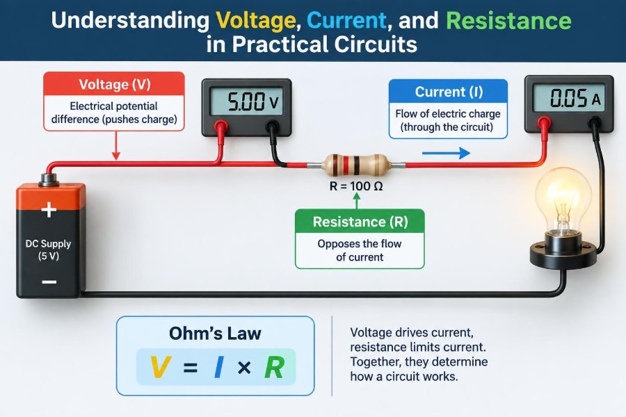
Voltage, current, and resistance describe different aspects of electrical behavior. Voltage expresses an electrical potential difference, current is the rate at which electric charge moves, and resistance describes how strongly a component or path opposes that movement.
They are related, but they are not interchangeable. A 9 V battery can have voltage even while sitting unconnected on a desk; current flows only when a complete conductive path allows charge to move.
🔋 Voltage Is Electrical Potential Difference
Voltage is measured in volts (V) and always exists between two points. Saying that one terminal is at 5 V usually means it is 5 V higher in electrical potential than a chosen reference point, often called ground.
A useful mental model is stored energy per unit charge. A greater potential difference gives each coulomb of charge more capacity to transfer energy as it moves through a circuit. That energy may become light, heat, sound, motion, or processed information.
🌊 Current Is Charge in Motion
Current is measured in amperes (A). One ampere means one coulomb of charge passes a point in a circuit each second. In electronics, currents are often much smaller, so milliamperes (mA) and microamperes (µA) are common.
Current requires a closed path. If a switch is open, a voltage may appear across its contacts, but ideally no meaningful current passes through it. Close the switch and the circuit conditions change immediately.
🧱 Resistance Limits Current Flow
Resistance, measured in ohms (Ω), indicates how much a material or component resists current for a given applied voltage. A larger resistance allows less current at the same voltage; a smaller resistance allows more.
Resistance is useful, not inherently wasteful. A resistor can set an LED current, establish a transistor bias voltage, divide a supply voltage for a sensor input, or safely discharge a capacitor after power is removed.
📐 Ohm’s Law Connects the Basics
For an ohmic resistor operating within its normal range, Ohm’s law is:
V = I × RRearranging it gives I = V / R and R = V / I. If 12 V is applied across a 1 kΩ resistor, the expected current is 12 mA. That number is not a guess; it follows from the resistor value and the voltage actually across it.
Ohm’s law is a model for a relationship, not a promise that every device behaves like a fixed resistor. LEDs, diodes, motors, transistors, and batteries often have nonlinear or changing behavior.
🔄 A Practical Water Analogy—With Limits
Water pressure resembles voltage, water flow rate resembles current, and a narrow pipe resembles resistance. This analogy explains why more pressure can drive more flow through the same restriction.
Its limitation is that electrical charge does not get used up like water leaving a tank. Charge circulates through a closed circuit. What components consume or convert is energy, not charge itself.
⭕ Why a Complete Loop Matters
Conventional current is described as flowing from the positive supply terminal, through the load, and back to the negative terminal. Electron motion in metallic conductors is in the opposite direction, but conventional current remains the standard notation in circuit analysis.
The return path is just as real as the outgoing path. A loose ground wire, corroded return connection, or narrow shared trace can create failures even when the positive supply side looks correct.
🧭 Polarity and Reference Points
Voltage has polarity. A meter reading of +5 V means its red probe is at a higher potential than its black probe by 5 V. Reversing the probes produces approximately −5 V.
“Ground” is often simply the circuit’s chosen zero-volt reference. It is not automatically Earth, and it is not automatically safe to touch. In mains-powered equipment, protective earth and circuit ground require careful treatment and may not be the same node.
🪫 Open-Circuit Voltage Versus Loaded Voltage
Measuring a battery with nothing connected reveals its open-circuit voltage. This measurement can be useful, but it does not fully show how the battery performs when it must deliver current.
When a load is connected, voltage may fall because real sources have internal resistance and electrochemical limits. A battery that appears acceptable with no load can still be unable to run a high-current device reliably.
🧰 Sources Also Have Internal Resistance
A practical voltage source can be modeled as an ideal source in series with a small internal resistance. As load current rises, the voltage lost inside the source rises too.
This explains why a bench supply may enter current limiting, why a long USB cable causes slow charging, or why a starter motor can pull a vehicle battery voltage down. The source is not “creating less voltage”; part of the available voltage is being dropped internally.
💡 Reading a Simple LED Circuit
Consider a 5 V supply, a red LED, and a series resistor. The LED may have a forward voltage near a few volts, depending on its type, current, and temperature. The resistor must absorb the remaining supply voltage and set a safe current.
If a hypothetical LED drops 2 V at the desired operating point and the target current is 10 mA, the resistor calculation is (5 V − 2 V) / 0.01 A = 300 Ω. A nearby standard value can be selected, then the actual current and brightness verified.
🧮 Voltage Drops Are Not Lost Information
A voltage drop across a component tells you where electrical energy is being transferred or dissipated. Across a resistor, that energy becomes heat. Across an LED, some becomes light and some heat. Across a motor, energy becomes mechanical output plus losses.
In a series circuit, the individual voltage drops add up to the source voltage. This is Kirchhoff’s Voltage Law: around a complete loop, voltage rises and drops balance when signs are handled consistently.
🧵 Series Circuits Share Current
Components in series have one path, so the same current flows through each component. Their resistances add: two 100 Ω resistors in series produce 200 Ω total resistance.
The source voltage divides among the resistors according to their values. With 10 V across a 100 Ω and 200 Ω series pair, the current is about 33.3 mA, so the drops are about 3.33 V and 6.67 V respectively.
🛣️ Parallel Circuits Share Voltage
Components in parallel connect across the same two nodes, so each branch sees the same voltage. The branch currents can differ because each branch resistance can differ.
Total current equals the sum of all branch currents. Adding a parallel branch lowers the equivalent resistance and makes the source supply more current, provided it can do so without reaching its limits.
| Connection type | Same quantity | What adds | Typical use |
|---|---|---|---|
| Series | Current | Resistance and voltage drops | LED current limiting |
| Parallel | Voltage | Branch currents | Devices on a supply rail |
🌡️ Power Explains Heating and Work
Power is the rate of energy transfer, measured in watts (W). The most useful circuit relationship is P = V × I. For resistors, equivalent forms are P = I²R and P = V²/R.
A 1 kΩ resistor across 12 V dissipates 0.144 W. A small resistor rated for only 0.125 W would be operating beyond its rated dissipation under those conditions, even though the voltage and current may initially look modest.
🔥 Resistor Power Ratings Need Margin
A resistor’s resistance value determines current, while its power rating determines how much heat it can safely dissipate under specified conditions. These are separate specifications.
Choose a rating with reasonable margin, especially in enclosed equipment, high ambient temperature, or circuits with supply transients. Derating may be necessary because a resistor’s permitted dissipation falls as its surroundings become hotter.
- Calculate normal dissipation from the worst expected voltage or current.
- Consider tolerance in the resistor and supply.
- Check whether fault conditions can impose greater power.
- Allow space for airflow and avoid heating sensitive parts nearby.
📏 Wires Have Resistance Too
Wires are often treated as ideal conductors in introductory diagrams, but every real wire and printed-circuit-board trace has resistance. Longer paths, smaller cross-sectional area, and higher-resistivity materials increase it.
At low current, the effect may be negligible. At higher current, cable resistance produces voltage drop and heat. A remote load can receive substantially less voltage than the supply terminals, particularly with thin or long leads.
🧊 Temperature Changes Electrical Behavior
Most metal conductors increase in resistance as temperature rises. A copper wire or conventional resistor therefore changes slightly when it heats. This can increase voltage drop in power wiring and alter precision measurements.
Other components behave differently. Thermistors are designed to have strong temperature-dependent resistance, while semiconductors can exhibit changes that cannot be represented by one fixed resistance. Design calculations should use relevant datasheet conditions where accuracy matters.
🧲 Loads Are Not Always Resistive
A heater is close to a resistive load, but motors, transformers, coils, and capacitors behave differently because they store energy in magnetic or electric fields. Their current can change over time and can depend on frequency.
A motor may draw a large current at startup because it is not yet spinning fast enough to generate substantial back electromotive force. A relay coil can produce a voltage spike when switched off. These behaviors require protection methods beyond a simple Ohm’s law calculation.
📉 Nonlinear Devices Need Operating Points
For a fixed resistor, doubling voltage approximately doubles current. For a diode or LED, a small voltage change can cause a large current change once forward conduction begins. The device’s current-voltage curve is nonlinear.
This is why LEDs are usually driven with a series resistor or a regulated constant-current driver. Connecting an LED directly across a suitable-looking voltage source can produce excessive current because its forward voltage does not reliably set its own safe operating current.
🧪 Measuring Voltage Correctly
A voltmeter is connected in parallel with the two points being compared. Modern digital multimeters generally have high input resistance, so they draw little current and usually disturb a low-power circuit minimally.
Start with the correct measurement function and an appropriate range if the meter is not autoranging. Measure the supply at its terminals, then measure at the load. The difference can reveal wiring losses, switch resistance, or poor connections.
🔌 Measuring Current Without Creating a Short
An ammeter is connected in series, so the circuit current passes through it. In current mode, a meter has a low-resistance internal shunt. Placing it directly across a voltage source can effectively short the source.
Move the probe to the correct current jack, begin on a high-current range when uncertain, and restore the probe afterward. For larger currents or inconvenient wiring, a clamp meter designed for the relevant current type can be safer and less disruptive.
🧑🔧 Measuring Resistance Safely
Resistance measurement uses a small internal meter source, so the circuit should normally be powered off. Stored energy in capacitors should also be discharged safely before probing.
Measuring an in-circuit resistor can be misleading because parallel paths influence the result. When an accurate component value matters, isolate at least one lead if practical. Never assume a resistance reading alone proves that a component functions correctly under load.
🧩 The Voltage Divider Is a Controlled Ratio
Two resistors in series can produce a lower voltage at their junction. If the output is unloaded, the ratio is determined by the resistor values: the lower resistor’s share equals its resistance divided by the total resistance.
A divider is excellent for a high-impedance sensing input, but it is a poor power supply for a load that draws meaningful current. The load effectively becomes another parallel resistance, shifts the ratio, and may cause the expected voltage to collapse.
🧯 Short Circuits and Overcurrent
A short circuit is an unintended low-resistance path. It can cause a very high current, limited by the source, wiring, contacts, and protection devices. Heat rises rapidly because even small resistance becomes significant when current is large.
Fuses, circuit breakers, electronic current limiting, and properly sized conductors reduce the consequences of faults. They are not substitutes for correct wiring, insulation, enclosures, and safe working procedures.
🛡️ Safety Depends on More Than Voltage
Electrical hazard depends on available voltage, possible current path through the body, source capability, duration, environment, and whether energy is stored in capacitors or batteries. Mains circuits and high-energy battery systems deserve particular caution.
Use appropriately rated instruments and probes, avoid working alone on hazardous equipment, and de-energize whenever possible. If measurements on energized mains equipment are necessary, they require training, suitable procedures, and equipment rated for the installation category.
🔍 A Logical Troubleshooting Sequence
Random probing often wastes time. Start with the circuit’s intended operation, then test the simplest assumptions in an order that narrows the fault.
- Inspect for loose connectors, damaged insulation, discoloration, and incorrect component orientation.
- Verify the source voltage under the actual load.
- Follow the supply path, checking voltage before and after connectors, switches, fuses, and wiring.
- Measure current only when the circuit arrangement and meter setup are understood.
- Compare findings with expected voltage drops, current, and power.
A component with the correct voltage across it but no expected current suggests an open path or unexpectedly high resistance. A large voltage drop across a connection that should be nearly zero suggests unwanted resistance.
🚫 Common Misconceptions That Cause Errors
One common error is believing that a supply “pushes its rated current” into every device. A voltage supply maintains its target voltage within its capability; the connected circuit determines current. A supply’s current rating is usually a maximum capability, not a forced output.
Another error is treating zero volts as automatically harmless or meaningless. A 0 V measurement is always relative to the chosen reference, and a circuit can have dangerous energy or current elsewhere. A third is assuming thicker wires solve every issue; conductor size matters, but connectors, fuses, routing, heat, and fault protection matter too.
📋 A Compact Design Check Before Powering Up
Before applying power to a new circuit, calculate expected current and power, then identify the likely failure modes. Ask what happens if a load is disconnected, shorted, reversed, stalled, or connected to the highest expected supply voltage.
- Confirm voltage ratings for capacitors, semiconductors, and insulation.
- Confirm current ratings for traces, wires, switches, and connectors.
- Calculate resistor dissipation and account for temperature.
- Provide current limiting or protection where a fault could cause damage.
- Use a current-limited bench supply for first power-up when suitable.
🧠 The Core Principle to Carry Forward
Voltage provides the potential difference that can drive charge, current is the movement of that charge through a complete path, and resistance shapes how much current flows for a given voltage. Power connects those quantities to real effects: heating, motion, light, and device operation.
The strongest habit is to stop viewing values in isolation. Ask where voltage is measured, what path carries current, what limits it, and where power is dissipated. Those questions apply equally to a single LED circuit, a sensor board, a motor controller, and a power-distribution system.
Understand the path, measure the difference, and calculate the limits: voltage, current, and resistance become practical tools rather than disconnected definitions. 🔌📏⚡