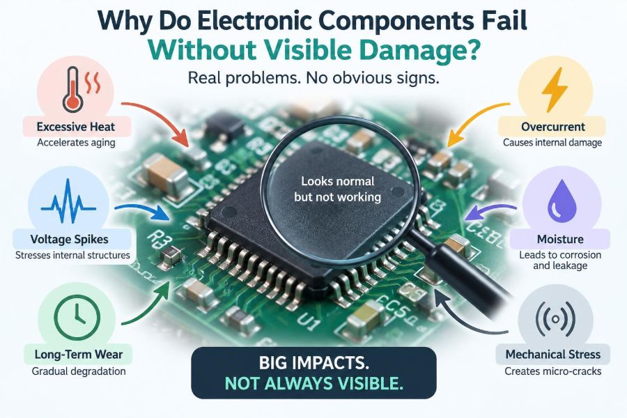

A controller board stops responding after a warm afternoon. A power supply passes a quick bench test but resets when a motor starts. A sensor works for weeks, then produces occasional nonsense readings that disappear before anyone can measure them.
When there is no scorch mark, cracked package, loose connector, or obvious smell, these failures can feel mysterious. They are not. Many electronic parts are damaged or pushed out of specification at scales too small to see, and the circuit may only reveal that damage under the right electrical, thermal, or mechanical conditions.
This matters to students learning troubleshooting and to professionals maintaining real equipment. Replacing a visibly normal part without understanding the stress behind the failure can create a short-lived repair—or damage the replacement in exactly the same way.
Electronic failures without visible damage are best understood as a gap between appearance and electrical behavior. The following causes and diagnostic habits help close that gap.
🔍 A Good-Looking Part Can Still Be Electrically Failed
Electronic components are defined by measurable behavior: resistance, capacitance, leakage current, timing, gain, switching speed, threshold voltage, and many other parameters. A part can look perfect while one of those parameters has drifted beyond what the circuit can tolerate.
A ceramic capacitor may have no mark at all but lose capacitance under DC bias. A MOSFET may look intact while its gate oxide has been weakened. An integrated circuit may run simple code yet fail at high temperature or during fast communication.
Visual inspection is therefore valuable, but it is only the first filter. It finds gross faults; it does not prove component health.
⚙️ Failure Is Often a Spectrum, Not an Instant Event
Some faults are abrupt: a fuse opens, a bond wire breaks, or a semiconductor junction shorts. Others develop through gradual wear, repeated overstress, contamination, or chemical change.
Before a component reaches a clear open or short circuit, it may become marginal. Its values may shift only when hot, under load, at a particular supply voltage, or after a vibration event. This is why an intermittent failure can be more difficult to diagnose than a completely dead board.
Thinking in terms of degradation also explains why “it worked yesterday” is not strong evidence that the design or environment is safe.
🔥 Heat Accelerates Hidden Aging
Temperature affects nearly every electronic mechanism. Higher temperature increases chemical reaction rates, raises leakage currents, softens some materials, and creates expansion differences between copper, solder, silicon, and plastic.
Heat does not need to be high enough to discolor a board to shorten useful life. A regulator enclosed with little airflow, for example, may remain below an absolute maximum temperature while still operating hot enough to accelerate capacitor aging and solder fatigue nearby.
The key distinction is between a brief temperature rating and reliable long-term operation. A datasheet limit is not automatically a preferred design target.
🌡️ Thermal Cycling Creates Mechanical Fatigue
Materials expand by different amounts as temperature changes. Silicon, package mold compound, solder, copper traces, and printed-circuit-board laminate are bonded together, so repeated heating and cooling creates stress at their interfaces.
Over many cycles, solder joints can develop microscopic cracks. These cracks may reconnect when the board is cool and open when it warms, producing failures that seem random. Large components, board-edge connectors, power transistors, and parts mounted near heat sources are common locations.
A hypothetical clue is a board that starts reliably after cooling but fails after ten minutes of operation. That pattern points more strongly toward thermal behavior than toward a purely static logic error.
⚡ Electrical Overstress Can Be Invisible
Electrical overstress, often abbreviated EOS, occurs when voltage, current, power dissipation, or energy exceeds what a component can safely handle. The event may be brief enough to leave no visible trace.
A voltage spike can puncture a semiconductor layer, a current surge can locally heat a metal connection, and a reverse-polarity event can force a diode or IC protection structure into an unintended conduction path. The device may fail immediately, degrade, or appear to recover until a later stress exposes the damage.
EOS is broader than lightning or dramatic mains faults. Inductive loads, wiring faults, hot-plugging, poor grounding, and switching transients are common sources.
🧲 Inductive Loads Produce Voltage Spikes
Motors, relays, solenoids, transformers, and long cables store energy in magnetic fields. When their current is interrupted, they resist the sudden change and can generate a voltage high enough to damage the switching device or disturb nearby circuitry.
A flyback diode across a DC relay coil provides a controlled path for this energy. Other applications may require a transient-voltage suppressor, snubber network, clamp circuit, or a driver designed for avalanche energy.
The protection choice matters. A simple diode reduces voltage effectively but can slow relay release; a faster clamp may be preferable when timing matters. Protection is engineering trade-off, not a universal one-part fix.
⚡ ESD Can Injure Semiconductor Inputs
Electrostatic discharge (ESD) is a rapid transfer of stored static charge. A person can create a discharge that is barely felt—or not felt at all—yet it can exceed the tolerance of a sensitive IC input.
Many devices include internal protection structures, but those structures have limited energy capability. An ESD event can cause immediate failure, or it can create latent damage that increases leakage or reduces later reliability.
Grounded work surfaces, wrist straps used correctly, antistatic packaging, and controlled handling are practical controls. In finished products, external ESD protection and thoughtful connector layout are often necessary because users cannot be expected to follow laboratory procedures.
🛡️ Internal Protection Is Not a Power Input
A frequent design mistake is assuming an IC’s input clamp diodes can absorb whatever reaches a signal pin. These diodes are usually intended to handle limited transient or fault current, often with external current limiting.
If a signal arrives while the IC supply is off, current may flow through a clamp diode and partially power an internal rail. This “back-powering” can create unpredictable behavior and may overstress the protection structure.
Series resistors, level shifters, proper sequencing, and dedicated protection devices help keep fault current within a safe range. The relevant limit is not merely voltage; it is the combination of voltage, current, duration, and available energy.
🔋 Supply Rails Can Be Wrong Even When a Meter Says They Are Fine
A digital multimeter is excellent for average DC voltage, but it can miss brief dips, ringing, switching noise, and startup sequencing problems. A nominal 5 V rail may measure correctly while momentarily dropping during a load step.
Microcontrollers, memory, radios, and analog converters can react strongly to these brief disturbances. The result may be a reset, corrupted data, false sensor reading, or communication fault rather than a permanently damaged component.
An oscilloscope, used with appropriate probing technique, is often needed to see the rail under realistic load. Probe ground leads that are too long can themselves make high-frequency ringing look worse or different than it is.
📉 Undervoltage Can Cause Damage Indirectly
Undervoltage does not always harm a component directly, but it can force a system into unsafe behavior. A motor driver may draw more current while trying to maintain torque, a relay may chatter, and a microcontroller may execute unreliably before its brownout protection activates.
Repeated relay chatter, for instance, creates extra contact arcing and load transients. A weak supply can therefore become the root cause of failures that appear mechanical or unrelated.
Use brownout detection, adequate supply margin, controlled startup, and load-transient testing. A supply should be assessed at the board, not only at the power-source terminals where cable resistance may hide the actual drop.
🌊 Ripple and Noise Stress Circuits Differently
Ripple is periodic variation on a DC supply; noise is a broader term for unwanted voltage disturbance. Either can create trouble even if the average rail voltage is correct.
Electrolytic capacitors with rising equivalent series resistance, or ESR, may no longer filter switching ripple effectively. Sensitive analog circuits can show drift or noise, while digital circuits may lose timing margin.
Good decoupling is local: capacitors must be near the IC power pins and connected with low-inductance paths. A large capacitor elsewhere on the board cannot fully replace small local decoupling for fast current demands.
🧪 Capacitors Age in More Than One Way
Capacitors are common suspects because their behavior depends strongly on construction and operating conditions. Aluminum electrolytic capacitors can lose electrolyte over time, especially when exposed to heat and ripple current. Their capacitance may fall while ESR rises.
Multilayer ceramic capacitors can crack from board flexure or assembly stress, sometimes creating intermittent shorts. Some ceramic dielectric types also lose effective capacitance with DC bias, temperature, and age.
Checking only capacitance can be misleading. In a switching supply, ESR, leakage, ripple-current capability, voltage rating, temperature rating, and package size may all matter. A replacement with the same printed capacitance is not necessarily equivalent.
🧱 Board Flex Can Crack Hidden Connections
A PCB bends when it is screwed into a warped enclosure, pressed during connector insertion, dropped, or handled by one edge. Surface-mount parts and solder joints experience that strain.
Cracks may occur underneath ball-grid-array packages, chip capacitors, large inductors, and connectors, where they are difficult or impossible to see without imaging. A fault may respond to gentle pressure, but pressing a powered board is risky and can create new faults.
Mechanical design is part of electrical reliability. Correct mounting points, connector support, panel alignment, and avoiding heavy components on unsupported board areas reduce hidden fatigue.
🪛 Vibration Loosens More Than Screws
In vehicles, industrial equipment, portable instruments, and appliances, vibration can fatigue leads and solder joints or cause connector fretting. Fretting is wear at a contact interface caused by tiny repeated motion.
The contact may retain enough pressure to look normal while oxide debris raises resistance. Low-level sensor signals and high-current power paths are both vulnerable, although their symptoms differ: noisy measurements in one case, heating or voltage drop in the other.
Locking connectors, strain relief, suitable contact plating, and vibration-aware layout are more durable answers than repeatedly reseating a connector.
💧 Moisture and Contamination Create Leakage Paths
Water does not need to form a visible puddle to affect electronics. Humidity, condensed moisture, cleaning residue, flux residue, dust, salts, and industrial pollutants can create conductive or partially conductive paths across a board.
High-impedance circuits are particularly sensitive. A tiny leakage current that is irrelevant in a power circuit can shift the voltage at an op-amp input, sensor node, or timing capacitor enough to cause faulty operation.
Contamination can also promote corrosion, especially where voltage is present. Cleaning must be compatible with the assembly and thoroughly dried; an unsuitable cleaning process can spread residue or trap moisture rather than solve the problem.
🧂 Corrosion Often Starts Where You Cannot See It
Connector contacts, vias, component leads, and copper beneath coatings can corrode before the damage becomes obvious. Surface finish may hide early chemical changes, while a connector shell can conceal the actual contact interface.
Corrosion increases resistance, weakens solderability, and can eventually open a circuit. In humid or salty environments, conformal coating, sealed enclosures, appropriate connector selection, drainage, and controlled venting may be needed.
Coating is not magic. It must cover the intended areas, cure correctly, and avoid interfering with connectors, heat dissipation, adjustment points, or components that should not be coated.
🔌 Connectors Can Fail While Looking Fully Seated
A connector may be latched and still have a poor electrical connection. Causes include worn plating, insufficient contact force, misaligned terminals, contamination, damaged crimp barrels, and cable strain transferred into the contact.
Voltage-drop testing under load is often more revealing than an unpowered continuity test. A connection that reads near zero ohms on a meter may develop a meaningful drop only when carrying current.
For a suspected ground fault, measure the voltage between the load ground and the source ground while the load operates. Any unexpected rise indicates resistance somewhere in the return path.
🧠 Semiconductor Damage May Shift Parameters First
Transistors and integrated circuits do not always fail as obvious shorts or opens. Gate leakage can rise, transistor gain can change, reference voltages can drift, and input thresholds can move.
These changes reduce design margin: the comfortable gap between normal operating conditions and the point where a circuit stops behaving correctly. A marginal device may pass a room-temperature test but fail at temperature extremes, high speed, or low supply voltage.
Replacing the IC may restore operation, but the investigation should continue. A damaged IC is often evidence of a system-level problem such as an overvoltage transient, poor power integrity, or an incorrectly driven interface.
⏱️ Timing and Signal Integrity Failures Leave No Burn Mark
Fast digital signals are not simply “high” and “low.” Trace impedance, edge rate, return-current paths, reflections, crosstalk, and termination affect whether a receiver recognizes each transition reliably.
A board can work with a short test cable but fail with its intended cable length. It can work in a laboratory but fail after a component substitution changes edge speed. Nothing needs to be physically broken for this to occur.
Oscilloscope bandwidth, probe choice, grounding, and trigger setup affect what is observed. When diagnosing fast signals, measurement technique is part of the circuit being evaluated.
📡 EMI Can Mimic a Component Failure
Electromagnetic interference, or EMI, is unwanted electromagnetic energy that couples into a circuit through conduction, radiation, capacitive coupling, or inductive coupling. It can cause resets, false triggers, communication errors, and sensor noise.
A nearby motor, switching converter, radio transmitter, or relay can expose a weakness in filtering, grounding, shielding, or cable routing. The component may be healthy, but the system lacks enough immunity to its environment.
Ferrites, filters, shielding, cable routing, enclosure bonding, and improved return paths can help, but each should be selected based on the coupling path. Adding a random ferrite without identifying the mechanism is unreliable troubleshooting.
🧭 Grounding Problems Are Often Return-Path Problems
Current always returns to its source, and the path it takes matters. If a high-current motor return shares impedance with a sensitive sensor or logic reference, voltage drops along that shared path can be interpreted as signal changes.
This is sometimes called ground bounce or common-impedance coupling. It can produce symptoms that resemble a bad sensor, faulty ADC, or unstable microcontroller.
Separate noisy and sensitive return paths where appropriate, use a continuous reference plane when practical, and place decoupling so transient current loops are small. “Ground” is not a single perfect node across a real board.
🔄 Latch-Up Is a Hidden High-Current Failure Mode
Some CMOS integrated circuits can enter a low-resistance internal conduction state called latch-up. It may be triggered by input voltage outside the supply rails, fast transients, improper sequencing, or injected current.
Once latched, the device can draw excessive current until power is removed or the condition clears. If the supply can deliver enough current, heating can permanently damage the IC even though no external sign remains.
Current limiting, proper input protection, correct sequencing, and following pin-voltage limits reduce this risk. A device that becomes unusually warm after a transient deserves prompt investigation.
🧬 Manufacturing Defects Can Be Latent
Not every hidden failure is caused in the field. A marginal solder joint, damaged component from assembly handling, insufficient cleaning, counterfeit or improperly stored parts, and process variation can create a latent defect.
Such defects may survive initial functional test because the test does not reproduce the later temperature, vibration, load, or humidity condition. This is why manufacturing test strategy must reflect realistic failure mechanisms rather than checking only whether the product turns on.
For repair work, avoid assuming that a new-looking board is fault-free. For production, traceability and process control make patterns easier to identify when failures emerge.
📦 Storage and Handling Can Degrade Parts Before Use
Moisture-sensitive packages can absorb humidity during storage. During high-temperature soldering, absorbed moisture may expand and damage the package internally, a phenomenon sometimes called popcorn cracking because of its mechanism rather than its appearance.
Electrostatic exposure, bent leads, oxidation, and improper temperature storage can also affect components before assembly. The consequences may not appear until the board is powered or thermally cycled.
Follow component handling guidance, use suitable dry storage where required, and avoid treating all packages as equally robust. A careful assembly process begins before the soldering iron or reflow oven is used.
🧰 Start Diagnosis With Symptoms and Conditions
Random probing wastes time. Start by recording exactly what fails, when it fails, and what makes it recover. Does the fault depend on temperature, input load, cable movement, vibration, supply source, humidity, startup order, or elapsed operating time?
Then form a testable hypothesis. For example, a reset during motor startup suggests measuring rail droop and switching transients; a sensor offset that follows humidity suggests investigating leakage and contamination.
- Reproduce the fault safely and consistently.
- Compare the failing unit with a known-good unit where possible.
- Measure voltages, currents, temperatures, and signals at the moment of failure.
- Change one relevant condition at a time.
- Document observations, including tests that did not support the hypothesis.
A diagnosis is stronger when it explains both the observed symptom and why other likely causes do not fit.
📏 Choose Measurements That Match the Failure
Every instrument has limits. A multimeter is ideal for many DC checks; an oscilloscope reveals time-varying voltage; a thermal camera can identify abnormal heating; an LCR meter characterizes inductance, capacitance, and resistance under specified conditions.
In-circuit measurements require caution because parallel paths can distort results. A diode reading may include protection networks, and a capacitor measurement may include other capacitors or circuit paths. Lifting one terminal can clarify a result, but only after considering the risk of board damage.
| Observed pattern | Useful first checks | Possible hidden mechanisms |
|---|---|---|
| Fails only when warm | Temperature, rail ripple, solder-joint behavior | Thermal drift, fatigue crack, rising leakage |
| Resets during load changes | Supply at the load, current, transient waveform | Voltage droop, ground bounce, inductive spike |
| Intermittent with movement | Connectors, strain, flex response | Fretting, cracked solder, broken conductor |
| Erratic analog reading | Leakage, reference rail, noise, contamination | Moisture path, EMI, degraded capacitor |
🌡️ Use Temperature Carefully as a Diagnostic Tool
Gentle heating or cooling can help reveal temperature-dependent faults, but uncontrolled thermal shock can damage components or create misleading results. Use methods appropriate to the equipment and observe safety limits.
If heating a particular area consistently causes failure, do not immediately declare the nearest IC guilty. Heat spreads, resistance changes elsewhere, and mechanical stress can also change. Narrow the area and verify with electrical measurements.
Likewise, a cold spray response can implicate a thermal mechanism without proving the exact component. It is a clue, not a final diagnosis.
🚫 Common Troubleshooting Shortcuts That Mislead
Several habits create false confidence. Continuity does not prove a low-resistance connection under load. A component that measures normally at room temperature may still fail dynamically. Replacing parts until the symptom disappears does not establish root cause.
- Do not judge a power rail only by its average voltage.
- Do not use an absolute maximum rating as a normal operating target.
- Do not bypass fuses or protection parts to “see what happens.”
- Do not assume a replacement part has equivalent ESR, speed, voltage rating, or thermal behavior.
- Do not ignore the possibility that the test setup is injecting noise or creating a ground loop.
Fast repair and sound engineering are not opposites, but both improve when evidence guides each next step.
🛠️ Design for Margin Instead of Barely Passing
Reliable electronics tolerate realistic variation in supply voltage, temperature, component values, load current, assembly, aging, and environmental exposure. That tolerance is margin.
Margins can be created through derating, adequate cooling, transient protection, robust layout, sensible component selection, controlled impedance where needed, and fault-tolerant firmware. The best choice depends on the consequence of failure and the actual environment.
Overdesign is not always efficient; unnecessary cost, size, and power can be real drawbacks. The goal is informed margin based on credible stresses, not indiscriminate oversizing.
📋 Read Datasheets Beyond the Headline Rating
A component’s headline voltage or current rating rarely tells the whole story. Look for maximum junction temperature, thermal resistance, safe operating area, pulse limits, derating curves, ripple-current limits, recommended layout, ESD notes, and test conditions.
For semiconductors, distinguish continuous current from short pulses and understand whether cooling assumptions match the real assembly. For capacitors, compare dielectric behavior, DC-bias characteristics, ESR, life conditions, and temperature capability.
Datasheets describe a component under defined conditions. A design succeeds when those conditions are connected honestly to the actual board, enclosure, load, and user environment.
🧩 Root Cause Includes the System Around the Part
When a component fails invisibly, the failed component is often the final weak link rather than the original cause. A MOSFET damaged by a spike, for example, may be functioning exactly as its environment allowed—until the environment exceeded its limits.
A useful root-cause statement identifies the stress, the path by which it reached the part, the protection or margin that was missing, and the corrective action. “IC failed” is an observation, not a complete explanation.
This system view prevents repeat failures and produces design improvements that survive beyond one repaired board.
✅ The Core Principle: Test Behavior Under Real Stress
Invisible electronic failure is not mysterious once the right question is asked. Instead of asking only, “Does this part look damaged?” ask, “Does this circuit behave within specification under its real voltage, current, temperature, timing, mechanical, and environmental conditions?”
That shift leads naturally to better measurements, better hypotheses, and better repairs. It also encourages designs that account for transients, aging, tolerances, and the fact that a component’s visible exterior tells only a small part of its story.
The most reliable way to understand hidden failures is to connect the symptom to the stress condition that exposes it, then verify the mechanism with appropriate measurement.
Electronic components can fail quietly, but careful observation turns many “mystery faults” into understandable engineering problems—and gives the next design a better chance to endure. 🔌🧪🛠️