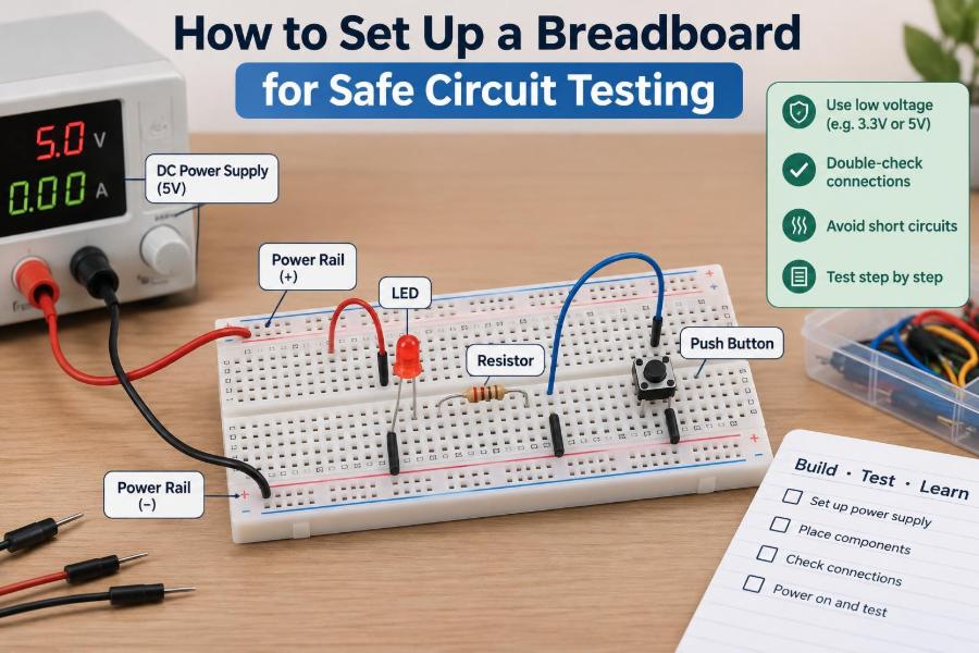

You have a new sensor, an LED project, or a circuit idea that looks straightforward on paper. The temptation is to push a few jumper wires into a breadboard, connect a battery, and see what happens.
That first power-up is where small oversights become frustrating problems: a reversed component, a missing current-limiting resistor, rails that are not actually connected, or a power supply set much higher than intended. Usually the result is a circuit that does nothing. Occasionally, a component overheats or a power source trips.
A breadboard is designed to make experimentation quick, but its convenience can hide electrical connections from view. Safe circuit testing depends on understanding those hidden connections and following a deliberate setup routine.
Whether you are learning basic electronics or checking a prototype before soldering it, a well-organized breadboard makes faults easier to find and protects the parts you want to reuse.
🧱 Understand What a Breadboard Does
A solderless breadboard is a reusable platform for building temporary low-voltage circuits. Metal spring clips beneath the holes electrically join selected holes together, so components and wires can be connected without solder.
It is best suited to low-frequency, low-current prototypes: indicator LEDs, switches, simple analog circuits, microcontroller projects, and many sensor interfaces. It is not a general-purpose substitute for a printed circuit board.
Think of the board as a visible wiring harness. The plastic surface holds everything in place, but the unseen metal strips determine whether your circuit matches the schematic.
🔍 Read the Internal Connection Pattern
Most full-size breadboards have a central terminal area split by a long gap. On each side of that gap, five holes in a short row are commonly connected together. The two groups on opposite sides are not connected across the gap.
Long rows near the outer edges are usually power rails. Their connection pattern varies by board, so never assume that every hole along a colored line shares the same electrical node.
Look at the printing, packaging diagram, or underside before starting. When in doubt, check continuity with a multimeter rather than trusting color markings.
🗺️ Treat the Schematic as a Connection Map
A schematic shows electrical relationships, not physical positions. Lines and symbols indicate which points are electrically the same, while a breadboard layout must translate those relationships into holes and wires.
Before placing parts, identify the circuit’s main nodes: positive supply, ground, signal input, signal output, and any shared junctions. A node is simply every point intended to have the same electrical potential.
This habit prevents a common beginner error: arranging parts to resemble the schematic drawing even when the breadboard rows do not create the required connections.
⚡ Start with a Suitable Power Source
Choose a supply that matches the circuit and can be controlled safely. A current-limited bench supply is excellent for learning because it can show both voltage and unexpected current draw. USB power, battery packs, and regulated plug-in modules can also work when their voltage is appropriate.
For a first test, use the lowest supply voltage that lets the circuit operate correctly. Many digital circuits require a specific voltage range, while a simple LED test can often begin at a modest voltage.
Do not connect mains electricity, wall-outlet wiring, or high-voltage sources directly to a breadboard. Breadboards have exposed contacts, uncertain current capability, and no protective enclosure.
🔋 Verify Voltage Before Connecting the Circuit
Set the supply with no prototype connected. Measure its output using a multimeter: black probe to the negative terminal and red probe to the positive terminal. Confirm both the value and polarity.
Some adjustable modules have small controls that are easy to move accidentally. A supply labelled with a nominal value may also be unsuitable if it is unregulated or loaded differently than expected.
Write the intended supply voltage in your notes. That simple reference helps when troubleshooting later, especially when several adapters or battery packs are on the bench.
🛡️ Use Current Limiting as Your First Protection
Current limiting restricts how much current a source can deliver when a fault occurs. On a bench supply, set a conservative current limit before attaching a new circuit. If the circuit has a short, the supply reduces voltage or enters constant-current operation instead of delivering its maximum output.
Start low enough to protect delicate components, then increase only if you understand why the circuit needs more current. The correct setting depends on the circuit; there is no single safe value for every project.
If your source cannot limit current, add a suitable fuse, resettable protection device, or deliberately chosen series resistance where practical. These measures do not replace careful wiring, but they reduce the consequences of a mistake.
📏 Know the Breadboard’s Practical Limits
The contacts inside a breadboard are small and can develop resistance, especially after heavy use. High current can heat wires and contacts, create voltage drops, or damage the board. Motors, heaters, high-power LEDs, and large battery packs should usually use more robust wiring and a properly rated construction method.
Breadboards also add stray capacitance and inductance. At high frequencies or with fast digital edges, those unintended electrical effects can distort signals and make a circuit behave unpredictably.
Use a breadboard for early functional checks, then move demanding designs to a soldered prototype or PCB. That transition is an engineering decision, not a failure of the breadboard.
🧹 Prepare a Clear, Unpowered Workspace
Turn off or disconnect power before inserting, moving, or removing components. Place the board on a clean, dry, nonconductive surface with enough lighting to read labels and wire colors.
Keep loose wire clippings, screws, conductive jewelry, and drinks away from the working area. A tiny trimmed lead can bridge adjacent holes and create an intermittent fault that is surprisingly difficult to locate.
Organize components in trays or small containers. This is not merely tidy: it reduces the chance of selecting the wrong resistor or losing a part that later becomes a hidden short.
🎨 Establish a Consistent Wire-Color System
Use colors to reveal the circuit’s intent. Red is commonly used for positive supply and black or blue for ground. Other colors can carry signals, with one color reserved for a particular bus or control line.
Consistency is more valuable than any specific color convention. If orange is your sensor output wire, do not reuse orange for an unrelated power path on the same board.
Cut wires to a sensible length. Long looping jumpers obscure components and can snag probes; very short wires can pull loose or make changes awkward. Neat routing turns visual inspection into a useful diagnostic tool.
🔌 Build the Power Rails Deliberately
Connect the power supply leads to the chosen positive and ground rails only after verifying polarity. Mark the rails if the board’s printed colors are faded, absent, or inconsistent with your usual convention.
Many boards split a long rail into separate sections, often around the middle. If your design needs one continuous rail, join the sections with a jumper wire and verify that connection with the multimeter.
Do not automatically bridge every rail section. Separate rails can be useful for different voltages, analog and digital supply organization, or isolated test areas. Label each one so a later change does not create a cross-connection.
📐 Place Integrated Circuits Across the Center Gap
Dual in-line package integrated circuits are normally placed so they straddle the center gap. Each pin then sits in its own five-hole connection group rather than being shorted to the pin directly opposite it.
Align the notch or dot that marks pin 1 with your layout plan. Pin numbers usually proceed around the package, but always check the component datasheet rather than relying on memory.
Before applying power, inspect every IC pin. A bent pin may miss the contact strip, and a chip inserted one row off can connect pins in ways that are hard to see from above.
🧭 Check Component Orientation Before Insertion
Some components work in either direction, including ordinary resistors and many ceramic capacitors. Others are polarized and must be installed correctly. Common examples include LEDs, diodes, electrolytic capacitors, transistors, voltage regulators, and integrated circuits.
Identify the marking before mounting the part: an LED’s flat side or shorter lead, a diode band, a capacitor’s polarity stripe, or a device’s package marking. Lead length alone is not reliable after parts have been trimmed.
Reversed polarity can cause a circuit to fail quietly, but it can also damage a part. Check orientation against the datasheet symbol and the actual package, not only a simplified drawing.
💡 Always Limit LED Current
An LED is not connected directly across a voltage source in a typical breadboard test. Once it begins conducting, a small change in voltage can cause a large change in current. A series resistor provides the necessary control.
A practical calculation is R = (VS - VF) / I, where the supply voltage minus the LED forward voltage is divided by the intended LED current. Use the LED datasheet when available, and choose a conservative current for a first test.
For example, a hypothetical 5 V circuit with an LED dropping about 2 V needs a resistor to absorb the remaining voltage. The exact resistor depends on the desired current; do not copy a value blindly between different supplies or LED colors.
🧮 Confirm Resistor Values Before Use
Resistors can look nearly identical even when their values differ greatly. Read the color bands carefully, use a component label, or measure resistance with a multimeter before installation.
When measuring a resistor, keep it out of an energized circuit. A reading taken while it is connected in parallel with other components may not represent its actual value.
A wrong resistor can produce subtle symptoms: an LED that is dim, a transistor that never switches fully, a sensor reading that drifts, or an IC input held at the wrong logic level. Verification is faster than guessing.
🧠 Avoid Floating Inputs
A floating input is an input pin left without a defined high or low voltage. It may pick up electrical noise, retain charge, or switch unpredictably when a nearby wire moves.
Buttons and switches often need a pull-up or pull-down resistor. This resistor establishes a known default state when the switch is open, while the switch deliberately changes the input when pressed.
For microcontrollers, some internal pull resistors may be available, but their behavior and value range depend on the device. Read the documentation and make the intended default state explicit in both wiring and code.
🌍 Create One Clear Ground Reference
Voltage is always measured relative to something. In many small DC prototypes, the negative supply rail serves as the shared ground reference for the circuit.
If a sensor module, microcontroller, and separate regulated supply exchange signals, they often need a common ground for those signals to have a meaningful reference. Without it, a logic signal may appear erratic or fail to register.
There are exceptions, such as intentionally isolated interfaces. Do not tie grounds together blindly where mains-connected equipment, isolated converters, or specialized measurement systems are involved. Understand the isolation design first.
🧩 Add Decoupling Capacitors Near Active Devices
Digital ICs and many analog devices draw short bursts of current as they operate. A decoupling capacitor, placed between the local supply and ground near the device, supplies some of that transient current and helps reduce supply noise.
A small ceramic capacitor is commonly used for this purpose, but the appropriate capacitance and placement depend on the component and circuit. Follow the device datasheet where it gives recommendations.
On a breadboard, capacitor leads should be short and connected close to the IC supply pins. Placing one far away at the rail may provide less benefit because the intervening wiring has resistance and inductance.
🧪 Build and Test in Small Stages
Do not build a complicated circuit all at once if you can avoid it. Begin with power distribution, then verify the rails. Add one functional block at a time: perhaps an LED indicator, then a regulator, then a sensor, then the controller.
After each stage, test the expected voltage or behavior. If the project stops working after a new addition, the search area is small and the cause is easier to isolate.
This staged method mirrors professional bring-up practice. It is slower than rushing through assembly, but it saves time compared with debugging a board full of simultaneous unknowns.
📊 Make a Pre-Power Inspection Routine
Before connecting power, pause for a visual and electrical check. Compare the physical board with the schematic or your planned layout one connection at a time.
- Confirm supply voltage, polarity, and current limit.
- Check that polarized parts face the intended direction.
- Look for exposed wire ends touching nearby rows.
- Verify that no IC pin is accidentally bridged to another pin.
- Confirm resistor values and LED current limiting.
- Check whether split rails are joined or intentionally separate.
A systematic routine is more dependable than a quick glance, particularly after making several late changes.
🔎 Use a Multimeter Before and After Power-Up
With power disconnected, continuity mode can check intended connections and reveal accidental shorts. Remember that a beep does not always mean a fault: many components, capacitors, and parallel paths can affect the reading. Interpret it using the circuit diagram.
After power-up, measure voltage from each supply pin to ground. Check the power rails before probing signal pins. A missing supply or reversed polarity makes signal measurements misleading.
Use probe tips carefully. It is easy to slip and short adjacent rows, especially around fine-pitch adapter boards. Insulated grabber clips or hooks can make longer measurements safer and more repeatable.
🌡️ Watch for Early Warning Signs
During the first power-up, stay present. Watch the supply’s current display if it has one, and be alert for a component becoming warm, a smell of overheated material, unexpected dimming, or a supply voltage that collapses.
If anything seems wrong, disconnect power promptly. Do not continue testing in the hope that a hot component will settle down. Let parts cool, then inspect orientation, wiring, and expected current before trying again.
A component can be damaged without obvious external marks. If correcting the wiring does not restore expected behavior, replace the suspect part and retest the simplest possible version of the circuit.
🚫 Avoid Common Breadboard Short Circuits
Short circuits often come from misunderstanding rows rather than from dramatic wiring errors. A resistor lead inserted into the same five-hole group as another lead may bypass the resistor entirely. Two wires placed one row off can join a signal to power or ground.
Other frequent causes include stripped wire that is too long, jumper leads with damaged insulation, metal tools left on the board, and incorrectly placed regulator modules.
Use continuity mode to investigate a suspected short with power removed. Then remove branches of the circuit one at a time rather than randomly relocating wires.
🧯 Disconnect Power Before Every Modification
Moving a jumper while power is applied can briefly connect it to the wrong row. This may reset a microcontroller, corrupt a measurement, or short a supply through a component that was never meant to carry that current.
For low-energy circuits, an accidental touch may cause no visible damage, which can encourage careless habits. The safer routine is still simple: switch off, change the wiring, inspect it, then power up again.
There are controlled exceptions during troubleshooting, but live modifications should be limited to people who understand the circuit risks and have a clear reason for doing them.
🧰 Choose Jumpers and Leads That Fit Properly
Solid-core hookup wire is often easier to use on a breadboard because it stays where you bend it and makes dependable contact. Stranded wire can work, but loose strands may fray and adjacent contacts may be bridged.
Use wire gauges compatible with the breadboard holes. Oversized leads can weaken spring contacts; undersized leads may fit loosely and create intermittent faults when the board is bumped.
Pre-made jumper wires are convenient, but inspect them periodically. A broken conductor hidden inside insulation can imitate a complex circuit error until you test the lead directly.
📷 Document the Layout While It Works
Take a clear photograph of a working prototype and save the schematic, supply voltage, component values, and any code version used. A breadboard circuit can be changed in seconds, and memory is unreliable after several experiments.
For a more complex design, label functional areas or draw a simple placement map. Note jumper connections that cross the board or bridge split rails, since these are easy to overlook during reconstruction.
Documentation also helps distinguish a repeatable electrical problem from an accidental assembly change. That makes collaboration and future soldered versions much easier.
🧱 Recognize When a Breadboard Is the Wrong Tool
Move beyond the breadboard when the project handles significant current, must withstand vibration, operates at high frequency, contains dense surface-mount parts, or needs dependable long-term operation. These conditions demand controlled connections and physical support.
Perfboard, stripboard, adapter boards, and custom PCBs offer different trade-offs between speed, durability, cost, and electrical performance. A soldered prototype is often the appropriate next step after proving the circuit concept.
Likewise, circuits connected to mains power, high voltages, large energy-storage capacitors, or powerful batteries require specialized safety practices. Do not treat a standard breadboard as a safe platform for them.
🛠️ Troubleshoot Methodically When It Does Not Work
Start with the most fundamental question: are the correct voltages present at the correct points? Then verify ground continuity, component orientation, expected resistor values, and each connection in the signal path.
Change one thing at a time and record the result. Replacing multiple parts or rearranging many wires at once may hide the original cause and create a new one.
If possible, reduce the circuit to a known-good test. For example, test an LED and resistor alone before blaming a microcontroller output, or test a sensor’s supply before investigating its data protocol.
✅ Use a Repeatable Safe-Testing Sequence
A reliable workflow turns safety into a routine rather than an afterthought:
- Read the schematic, datasheets, and supply requirements.
- Plan power, ground, signal paths, and component placement.
- Build with power disconnected and use consistent wire colors.
- Inspect orientation, rail connections, and exposed conductors.
- Set and measure the supply voltage; apply current limiting where possible.
- Check for likely shorts, then power one stage at a time.
- Measure rails first, observe current, and stop if behavior is unexpected.
- Document the proven layout before expanding it.
The sequence is adaptable, but its order matters: verify the energy source before asking the circuit to do useful work.
🎯 The Core Principle of Safe Breadboarding
Safe breadboard testing is not about eliminating every possible mistake. It is about arranging the work so that mistakes are visible, limited in energy, and easy to diagnose.
Understand the hidden contact pattern, use a suitable low-voltage supply, control available current, verify polarity, and test incrementally. Those practices protect components while giving you better information about what the circuit is doing.
The most effective breadboard setup is one you can explain: where power enters, where current returns, what every wire connects, and what measurement should confirm each stage.
A safe breadboard is built through deliberate connections, controlled power, and repeated verification—not through confidence alone. With that approach, each prototype becomes a practical lesson in both circuit behavior and sound engineering habits. 🔌🧪🛠️