
A laboratory preamplifier produces a faint buzz whenever its bench supply is connected. A guitar pedal becomes noisier when a cheap USB adapter shares the outlet. A medical-adjacent prototype works perfectly on a battery, then behaves erratically on mains power.
It is tempting to blame the power supply immediately—and then make a simple rule: linear supplies are quiet and safe, while switching supplies are noisy and risky. That rule contains a small piece of truth, but it is not enough to design, buy, or troubleshoot reliable electronics.
Both linear power supplies and switching-mode power supplies can be safe for sensitive equipment. Both can also cause problems when their electrical performance, isolation, grounding, thermal behavior, and installation are poorly understood.
The useful question is not which topology wins in every situation. It is: what kind of safety and sensitivity matter for this circuit, in this environment, with this particular supply?
⚖️ Safety Has More Than One Meaning
In power-supply discussions, “safe” often mixes together several different concerns. Separating them prevents a great deal of confusion.
- Electric-shock safety: preventing hazardous mains voltage from reaching accessible low-voltage circuits or users.
- Equipment safety: avoiding overheating, overvoltage, excessive current, fire risk, or component damage.
- Signal integrity: preventing noise, ripple, interference, and unwanted ground currents from corrupting operation.
- Functional reliability: ensuring the device starts, runs, and recovers predictably under real loads.
A supply can be electrically isolated and still inject enough noise to disturb a sensor. Conversely, a very low-noise supply can be unsafe if it lacks adequate insulation, fusing, ventilation, or fault protection.
🔋 What a Linear Power Supply Does
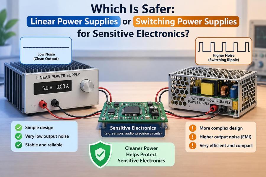
A conventional linear supply reduces mains voltage with a transformer, rectifies it to DC, smooths it with capacitors, and regulates the output using a transistor operating in its linear region. The regulating element behaves somewhat like a continuously adjustable valve.
Because the regulation process does not deliberately chop current at high frequency, its output can be very quiet in the radio-frequency sense. Its remaining ripple is usually related to the mains frequency and the rectifier charging cycle.
The transformer also provides galvanic isolation when correctly designed. Galvanic isolation means there is no intentional direct conductive path from the mains input to the low-voltage output.
⚡ What a Switching Power Supply Does
A switching-mode power supply, usually shortened to SMPS, regulates power by turning semiconductor switches on and off rapidly. Energy is transferred through inductors or transformers, then filtered and controlled using feedback.
Modern phone chargers, laptop adapters, LED drivers, server supplies, and many laboratory supplies use this approach. Switching allows smaller magnetic components and high efficiency, especially where the input-output voltage difference is large.
High-frequency switching is not inherently dangerous. It does, however, create fast voltage and current changes that demand careful filtering, layout, shielding, and electromagnetic compatibility design.
🧭 The Topology Does Not Certify the Product
A linear supply is not automatically safer because it contains a large transformer. A switching supply is not automatically unsafe because it uses fast switching. Protection and construction quality matter more than the label on the front panel.
A well-engineered SMPS may include reinforced isolation, input fusing, surge protection, overcurrent limiting, thermal shutdown, short-circuit protection, and carefully controlled emissions. A poorly built linear supply may lack a fuse, run its transformer too hot, or expose hazardous wiring inside an inadequate enclosure.
For mains-powered equipment, safety depends on the complete assembly: enclosure, connectors, creepage and clearance distances, protective earth strategy, insulation system, components, and manufacturing quality.
🛡️ Isolation Is the First Shock-Safety Question
For a supply connected to mains power, ask whether its output is isolated. An isolated output is usually preferable for low-voltage equipment that users can touch, connect to computers, or attach to external instruments.
Many linear supplies use a low-frequency isolation transformer. Many offline switching supplies use a high-frequency isolation transformer. Either can provide robust separation if its insulation and physical spacing are designed for the intended mains category and environment.
Some switching converters are non-isolated, such as a DC-DC buck converter fed from an already safe low-voltage source. These are perfectly useful within a device, but they must not be mistaken for a substitute for mains isolation.
🚧 Creepage, Clearance, and Real Construction
Isolation is more than placing a transformer on a circuit board. Clearance is the shortest distance through air between hazardous and accessible conductors. Creepage is the shortest path along an insulating surface.
Dust, humidity, contamination, manufacturing residue, board slots, wire routing, and connector placement can all affect whether an isolation barrier remains dependable. These details are invisible in many low-cost products, yet they are central to safety.
If a product must be used around people, mains wiring, or costly instruments, use an appropriately rated commercial unit or have a qualified engineer review the design. Visual inspection alone cannot establish compliance.
🌡️ Heat Is an Equipment-Safety Issue
Linear regulators dissipate the voltage difference between input and output as heat. If a supply receives 15 V and provides 5 V at 1 A, the regulator may need to dissipate roughly 10 W, excluding other losses. That is a serious thermal load.
Excessive heat shortens capacitor life, stresses semiconductors, and can create a burn or fire hazard if the enclosure and heat sinking are inadequate. A linear supply is often excellent at modest currents, but inefficient voltage conversion can make it impractical at higher power.
Switching supplies usually waste less power as heat. Their challenge is different: concentrated losses in switches, magnetics, rectifiers, and control components require sound thermal design and adequate airflow.
🔌 Overcurrent Protection Is Not Optional
Sensitive electronics can be damaged by a supply that delivers far more current than a wiring fault, failed component, or reversed connection can tolerate. Current capability is useful only when faults are managed safely.
Useful protections may include input fuses, output current limiting, foldback limiting, hiccup-mode protection, electronic shutdown, and thermal protection. Their behavior differs: some hold a limited current continuously, while others repeatedly attempt to restart.
For bench work, adjustable current limiting is particularly valuable. It can turn an accidental solder bridge from a destructive event into a visible warning: the output voltage drops and the supply enters current limit.
📈 Overvoltage Can Be More Dangerous Than Ripple
Designers sometimes focus heavily on millivolts of ripple while overlooking a more immediate risk: an output that rises above the load’s maximum voltage during a fault, transient, or incorrect adjustment.
Linear regulators can fail in ways that pass excessive input voltage to the output. Switching supplies can suffer feedback faults, startup overshoot, or control instability. Neither topology is immune.
Where an overvoltage could damage an expensive or safety-critical load, consider layered protection: a correctly rated supply, a local transient suppressor where appropriate, input fusing, supervisory shutdown, and—for certain linear applications—a crowbar or dedicated overvoltage protection circuit.
🌊 Ripple: The Low-Frequency Difference
Ripple is the unwanted variation remaining on a DC output. In a basic linear supply, reservoir capacitors charge near rectified AC peaks and discharge into the load between peaks. That creates a relatively low-frequency ripple component.
A regulated linear supply can reject much of this ripple, but rejection is finite and changes with load current, input-output voltage margin, frequency, and temperature. A regulator near dropout may allow more ripple through.
Low-frequency ripple is especially troublesome in audio circuits, precision measurement systems, and sensor front ends because it can appear as hum or a moving baseline rather than simply being filtered away.
📡 Switching Noise Is a Different Problem
An SMPS produces noise around its switching frequency and its harmonics, often accompanied by fast edges that extend to much higher frequencies. This noise can travel through output wires, ground connections, electric fields, magnetic fields, or capacitive coupling.
The output voltage may look acceptable on a basic meter while still disturbing an RF receiver, high-gain amplifier, high-resolution converter, or capacitive sensor. Noise is therefore not just a single “ripple” value.
A well-designed switching supply uses input and output filters, controlled switching transitions, snubbers, shielding where necessary, and a stable control loop. The resulting performance can be very good, but it is more dependent on design execution.
🔍 Measure Noise With the Right Instrument Setup
Oscilloscope measurements can exaggerate or hide supply noise. A long ground clip on a probe forms a loop antenna and can pick up switching fields that are not truly present at the measurement point.
For local rail-noise checks, use a short ground spring or very short ground connection, measure directly across the relevant capacitor, and set bandwidth intentionally. Compare results using the same probe, bandwidth limit, load, and physical setup.
Also measure under realistic conditions. A supply that looks clean at no load may behave differently during load steps, radio transmission bursts, motor operation, or processor activity.
🎧 Why Audio Circuits Often Reveal Supply Problems
Audio equipment makes power-supply problems easy to notice because the human ear is sensitive to hum, buzz, whine, and periodic ticking. A 50 Hz or 60 Hz hum and its harmonics often suggest low-frequency coupling or ground-loop behavior.
A higher-pitched whine, broadband hiss, or digital activity leaking into audio may point toward switching noise, poor layout, shared impedance, or a noisy digital load. The supply may contribute, but the circuit’s grounding and decoupling often determine how much becomes audible.
A quiet linear supply can help a microphone preamp, but it cannot fix an unbalanced cable routed alongside a noisy display cable or a poorly designed ground return.
🧪 Precision Sensors Need More Than a Clean Label
Strain gauges, thermocouple amplifiers, electrochemical sensors, photodiodes, and high-resolution data-acquisition circuits can respond to supply noise in subtle ways. Noise can modulate a reference, alter amplifier headroom, or couple into high-impedance inputs.
For these systems, the relevant question is often noise within a specific frequency band. A supply with modest high-frequency noise may be acceptable if the measurement bandwidth is low and filtering is appropriate. A low-frequency fluctuation may be more damaging if it lies directly in the measurement band.
Use local reference filtering, separate analog and digital power paths where justified, thoughtful grounding, and adequate decoupling. A linear post-regulator may be useful, but it is only one part of the measurement-chain design.
📻 RF and High-Speed Digital Loads Create Their Own Demands
RF receivers can be affected by conducted and radiated emissions from a supply, particularly when a switching frequency or harmonic lands near a sensitive band. Physical distance, shielding, filtering, and cable routing can matter as much as nominal output ripple.
High-speed digital systems have a different concern: rapid current demand. Processors, FPGAs, and transceivers need low impedance over a broad frequency range, often very close to their power pins. A remote “ultra-low-noise” supply cannot replace local decoupling capacitors and a well-designed power-distribution network.
In both cases, a compact switcher placed carefully and filtered locally may outperform a distant linear supply connected through resistive, inductive leads.
🧷 Common-Mode Noise Explains Many Surprises
Noise can appear between a supply output and earth even when the output is nominally floating. In isolated switching supplies, small capacitors used for electromagnetic-interference control can capacitively couple high-frequency energy across the isolation barrier.
This is often called common-mode noise. It may be harmless for many devices, yet it can interfere with touch-sensitive inputs, high-impedance measurements, audio connections, or instruments connected to protective earth.
Do not defeat protective-earthing arrangements casually to remove noise. Instead, identify the return paths, use suitable filtering or isolation methods, and verify that any change preserves safety.
🌍 Ground Loops Are Not a Linear-versus-Switching Verdict
A ground loop occurs when multiple conductive paths create a loop between pieces of equipment. Small voltage differences or induced currents around that loop can become unwanted signal currents.
This commonly happens when an earthed bench instrument connects to an earthed computer and an audio or measurement device. It can occur with either linear or switching power supplies.
Useful remedies depend on the application: balanced interfaces, single-point signal reference strategies, differential measurement, galvanic isolation in data paths, or carefully placed isolation transformers. Simply lifting earth can create a shock hazard and is not a general fix.
🧯 Surge Resistance Begins at the Input
Mains disturbances, switching of inductive loads, and nearby electrical events can produce transients. A supply’s ability to survive them depends on its input protection, component ratings, layout, and the installation environment.
Linear transformer-based supplies can benefit from fuses and input suppression components; switching supplies commonly add rectification, surge-limiting, filtering, and protective clamps. Neither approach makes a device invulnerable to every abnormal event.
For installations exposed to severe electrical environments, choose equipment designed for that environment and consider protection at the building or system level. A small plug-in supply should not be assumed to solve every surge problem downstream.
🔄 Load Transients Test Regulation Quality
A sensitive circuit may draw a nearly steady current, but many modern loads do not. Motors start, radios transmit, digital processors wake, and LEDs change brightness. A sudden demand can pull down a weak supply or cause control-loop ringing.
Linear supplies often respond smoothly but may be limited by transformer size, regulator bandwidth, and output capacitance. Switching supplies can respond quickly, but poor loop compensation can lead to overshoot, oscillation, or audible burst behavior.
Check the supply under the actual load profile. If a circuit resets when a transmitter activates, the root cause may be transient voltage drop rather than average current rating.
🧱 Local Decoupling Is the Load’s First Defense
Decoupling capacitors placed near active devices provide brief, local current pulses and reduce high-frequency rail impedance. They also keep fast load currents from flowing through long traces or cables where they can disturb other circuitry.
A typical design uses several capacitor types and values because real capacitors behave differently with frequency, bias voltage, temperature, and physical size. The exact choices should follow the device data sheet and board layout constraints rather than a universal recipe.
A good power supply cannot compensate for missing local decoupling. Likewise, good decoupling cannot correct a supply with inadequate voltage, current capacity, protection, or isolation.
🧹 Filtering Can Make a Switching Supply Suitable
When a switcher is the practical choice, additional filtering can reduce conducted noise reaching a sensitive load. Options include LC filters, ferrite beads, common-mode chokes, feedthrough capacitors, shielded inductors, and a low-noise post-regulator.
Filters must be designed carefully. An LC filter can interact with a converter’s feedback loop and create instability or worse transient behavior. Component current ratings, DC resistance, saturation, capacitor ripple rating, and damping all matter.
A useful architecture for mixed-signal equipment is a primary switching supply for efficient bulk conversion followed by local filtering and, where needed, linear regulation for especially sensitive rails.
🏗️ Physical Layout Often Decides the Outcome
Current loops with large area radiate more strongly. High-current switching loops, transformer nodes, diode paths, and fast gate-drive paths should be compact and kept away from sensitive analog traces and connectors.
On a complete product, separate noisy power-conversion regions from input amplifiers, references, antennas, and high-impedance nodes. Route return currents deliberately rather than treating ground as a featureless plane.
With an external adapter, cable placement matters too. Moving a switching brick away from a sensor cable or audio input may reduce interference more effectively than changing the nominal supply type.
🧰 Bench Supplies Need Practical Safety Features
For development work, a bench supply should be chosen for more than its ripple specification. Clear voltage and current controls, current limiting, reliable terminals, sensible polarity markings, stable behavior at startup, and adequate insulation all improve daily safety.
Before connecting a new prototype, set a conservative current limit and verify the output voltage with the load disconnected. If the circuit has large input capacitors, expect a brief charging surge and set the limit with that in mind.
For very low-current analog experiments, a battery or a well-filtered linear bench supply can simplify troubleshooting. For higher-power work, an efficient protected switching bench supply may be the more sensible and safer thermal choice.
🪛 Beware of Unverified Modules and Adapters
Low-cost converter modules are useful for learning and prototypes, but their ratings may not describe continuous operation in a closed enclosure, high ambient temperature, or fault conditions. Some have minimal input protection and no meaningful output isolation.
Inspect for obvious warning signs: exposed mains terminals, inadequate enclosure, questionable connectors, no strain relief, undersized wiring, missing fuses, and unclear input ratings. These observations cannot prove a product safe, but they can reveal reasons not to use it.
Never place a bare mains-connected module where it can be touched or where conductive debris can fall onto it. Treat mains-side work as a separate hazard from ordinary low-voltage prototyping.
📋 Compare the Choices by Application
| Need | Often favorable approach | Reasoning |
|---|---|---|
| Low-power audio or precision analog prototype | Linear supply or filtered switcher with local regulation | Low-frequency and high-frequency noise both deserve attention. |
| Portable or battery-powered device | Switching converter | Efficiency and low heat are usually critical. |
| High-current low-voltage rail | Switching converter | A linear regulator may dissipate impractical heat. |
| RF receiver or sensitive instrument | Either, after emission testing and layout review | Conducted and radiated noise paths determine success. |
| Human-accessible mains-powered product | Appropriately rated isolated supply | Isolation and safety construction matter more than topology. |
This table is a starting point, not a substitute for evaluating the actual load, enclosure, environment, and applicable requirements.
🧠 A Better Selection Process
Start by writing down the electrical needs rather than selecting by reputation. Specify output voltage tolerance, maximum and typical current, allowed temperature rise, required isolation, acceptable noise band, load-transient behavior, and connection to other equipment.
- Determine whether mains isolation is required.
- Estimate worst-case power and thermal dissipation.
- Identify sensitivity: audio, precision analog, RF, digital, or mixed-signal.
- Consider the complete current-return and grounding arrangement.
- Choose protections for overload, short circuit, reverse connection, and overvoltage as appropriate.
- Test the proposed supply under realistic load and connection conditions.
This process often leads to a hybrid answer rather than a purely linear or purely switching one.
⚠️ Mistakes That Cause Avoidable Failures
One common mistake is choosing a supply with enough average current but no margin for startup or pulse loads. Another is adding a large filter capacitor without checking inrush current, regulator stability, or connector stress.
Designers also sometimes use a low-noise supply but route its output alongside noisy motor wiring, or connect every ground indiscriminately and then blame the supply for the resulting interference.
Finally, never assume that an adapter’s low-voltage label means every connected cable and peripheral is safe. Ground references, USB shields, test equipment, and external antennas can introduce unexpected paths.
✅ When Linear Supplies Are the Safer Practical Choice
A linear supply is often a strong practical choice when power is modest, heat can be managed, and low conducted and radiated switching noise would complicate a sensitive analog task. Its simpler noise spectrum can make debugging easier.
It is also appealing in educational laboratories because transformer isolation and straightforward circuitry help students see each stage of AC-to-DC conversion. Yet it still needs correctly rated fusing, insulation, enclosure design, thermal management, and protection against regulator faults.
Choose linear because its trade-offs suit the job—not because “linear” is synonymous with safe.
✅ When Switching Supplies Are the Safer Practical Choice
A switching supply is often the safer practical choice when a linear alternative would run dangerously hot, require an oversized transformer, or waste too much energy. This is common in high-current rails, portable systems, and compact equipment.
A quality isolated SMPS can offer excellent fault protection and low heat while meeting demanding electrical safety requirements. Its noise must be managed, but noise is an engineering constraint rather than a disqualifying flaw.
Choose switching when efficient conversion, thermal margin, size, and protected operation outweigh the added electromagnetic-design work.
🏁 The Core Principle: Evaluate the Whole Power System
The linear-versus-switching debate becomes useful only when it is tied to a real application. Shock safety comes from isolation, insulation, earth strategy, enclosure design, and fault protection. Equipment safety comes from proper ratings, thermal design, and controlled fault behavior.
Signal quality comes from the supply, but also from layout, decoupling, filtering, cable routing, grounding, and the frequency range in which the load is sensitive. A quiet output specification alone does not describe all of those factors.
The best supply is the one whose safety architecture and electrical behavior have been matched to the system—not the one that belongs to a favored topology.
For sensitive electronics, neither linear nor switching power supplies are universally safer; a properly isolated, protected, thermally sound, and noise-appropriate power system is the safer choice. 🔌🛡️📐