
A board that will not turn on can make even a simple repair feel mysterious. The connector looks fine, there are no burned parts, and a quick continuity check finds nothing obvious. Yet somewhere on the PCB, a component or connection is preventing the circuit from doing its job.
Voltage measurements turn that mystery into a traceable path. Every working circuit distributes electrical potential from a source, through protection and regulation stages, to loads such as processors, sensors, LEDs, and motors. When the expected voltage disappears or changes unexpectedly, the location of that change is evidence.
The key is not to probe parts at random. Good troubleshooting compares what the circuit should do with what it actually does, moving from known points toward unknown ones. A multimeter then becomes less of a meter and more of a map.
This method will not identify every defect by itself. Intermittent faults, high-speed signals, and faults that occur only under load may need an oscilloscope, thermal camera, or schematic. But for many no-power, low-voltage, and partially working boards, measured DC voltages provide the fastest useful starting point.
🧭 Start With a Circuit Story, Not a Random Probe
Before touching a probe, describe the board’s intended power path. A typical path is input connector, fuse or protection device, reverse-polarity protection, switching or linear regulator, distribution rail, and load. The exact order varies, but the idea is consistent: energy must pass through several checkpoints.
If a 12 V adapter powers a board that generates 5 V and 3.3 V, ask which rail is missing and what must happen before it appears. This prevents the common mistake of measuring an IC pin without knowing whether that pin is an input, output, enable, or feedback node.
📚 Gather Evidence Before Applying Power
Read board markings, connector labels, adapter ratings, and component reference designators. A label such as F1 usually indicates a fuse, D3 a diode, Q2 a transistor, and U5 an integrated circuit. These conventions are useful clues, not guarantees.
Look for a schematic, service documentation, a boardview file, or photographs of an identical working board. If none exists, datasheets for clearly marked regulators, controllers, and protection ICs can reveal pin functions and normal voltage ranges.
🛡️ Make the Measurement Safe for You and the Board
Use equipment rated for the voltage and energy available. Keep fingers behind probe guards, remove jewelry where appropriate, and avoid loose metal tools around an energized board. Mains-powered equipment and primary-side power supplies require substantially different precautions from low-voltage battery products.
For an unfamiliar or suspect board, a current-limited bench supply is safer than repeatedly connecting its normal adapter. Begin with the specified input voltage and a conservative current limit, then increase only when the board’s expected consumption and behavior justify it.
🔍 Inspect the PCB With Power Removed
Visual inspection is not a replacement for measurement, but it chooses better places to measure. Look for cracked connectors, lifted pads, corroded vias, discolored components, damaged traces, loose inductors, and swollen electrolytic capacitors.
Also inspect the underside. A solder bridge, fractured joint, or damaged via can be invisible from the component side. Remember that many failed semiconductors and ceramic capacitors show no visible sign at all.
⚡ Know What a Voltage Reading Actually Means
Voltage is a difference in electrical potential between two points. A multimeter reading of 5 V does not mean a point contains “5 volts”; it means that point is 5 V higher than the reference point connected to the black lead.
On most low-voltage PCBs, the reference is ground. Ground may be a large copper plane, connector negative terminal, mounting hole, or shielding can, but not every metal-looking point is ground. Confirm it with continuity testing while power is off when possible.
⏚ Choose a Reliable Ground Reference
Clip the black probe to a known ground point so the red probe is free to follow the circuit. This reduces slips and makes readings more repeatable. A ground pin at the DC input or a large ground test pad is often suitable.
Do not automatically use the negative terminal of every connector. Isolated power supplies, audio circuits, and high-side current-sense arrangements may have multiple references. A wrong reference can produce confusing readings that are technically real but diagnostically unhelpful.
🧰 Set Up the Multimeter Correctly
Select DC voltage, not AC voltage, resistance, current, or diode mode. Choose a range above the expected voltage if the meter is not autoranging. Verify the red lead is in the voltage input jack; leaving it in the high-current jack is a frequent and potentially damaging mistake.
Probe tips should be sharp enough to contact test pads and component leads without scraping away solder mask. Insulated probe adapters, hook clips, and fine needle probes can improve access, but they also demand careful handling to avoid bridging adjacent pins.
🔌 Verify the Source Before Blaming the PCB
Measure the adapter or battery first. A supply that reads correctly without load can still collapse when the board is connected, so measure it again at the board’s input connector while the board is powered.
If the voltage is missing at the connector, the fault may be an adapter cable, jack contact, battery protection circuit, or connector solder joint. Replacing components farther downstream would not solve that upstream problem.
🚪 Follow the Input Protection Path
After the input connector, measure each side of the fuse, polyfuse, reverse-polarity diode or MOSFET, surge suppressor, and input switch. The input voltage should appear on both sides of a healthy series element when the circuit is meant to be on.
A large voltage difference across a fuse, switch, or series diode identifies a useful boundary. It may mean the part is open, but it can also mean the board is drawing excessive current and a protection device has tripped or entered a high-resistance state.
🧯 Interpret Fuses and Resettable Fuses Carefully
A conventional fuse with supply voltage on one end and near-zero voltage on the other is open. With power removed, continuity can confirm that result. Do not simply bridge it: a blown fuse is often a symptom of a downstream short.
A resettable polymer fuse behaves differently. Under excessive current it heats and becomes resistive, producing a voltage drop. Let it cool, check for a short on the protected rail, and determine why it tripped before replacing it.
🧱 Locate the Board’s Power Rails
A power rail is a shared supply net, such as 12 V, 5 V, 3.3 V, 1.8 V, or a processor core rail. Large capacitors near ICs are often connected between a rail and ground, making their positive terminals convenient places to measure.
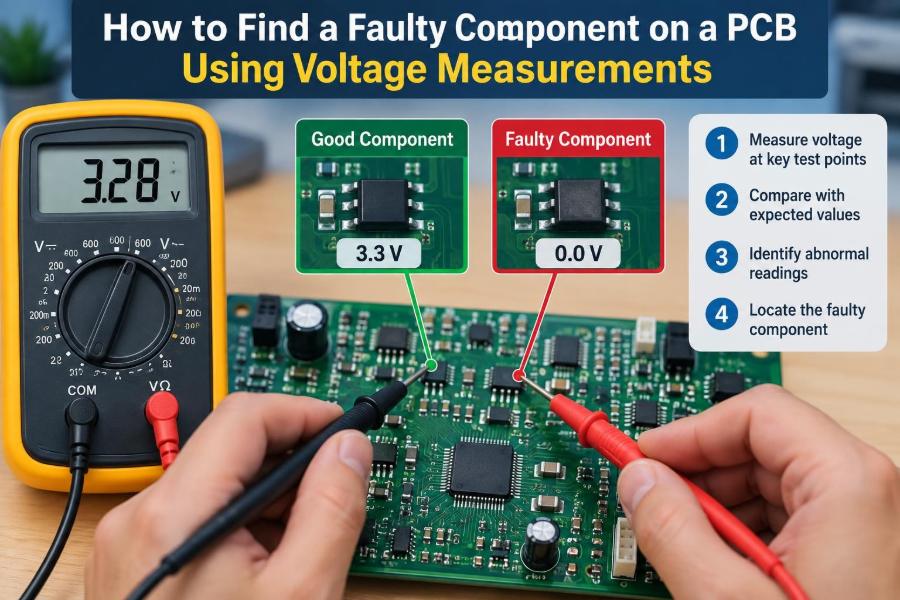
Mark the rails you find and note which ones are present. This builds a power map. For example, 12 V and 5 V may be healthy while 3.3 V is absent, immediately narrowing the search to the 3.3 V regulator, its enable path, and its load.
📊 Compare Expected and Measured Readings
Use a written table rather than trusting memory, especially on multilayer boards. “Present” is not always enough: a 5 V rail measuring 1.2 V is a major clue, while a rail within the tolerance stated by its regulator datasheet may be normal.
| Checkpoint | Expected condition | What an abnormal result suggests |
|---|---|---|
| Input connector | Specified supply voltage | Adapter, cable, jack, or battery fault |
| After fuse/protection | Nearly the input voltage | Open or tripped protection path |
| Regulator input | Enough headroom to regulate | Upstream interruption or excessive drop |
| Regulator output | Named output rail | Regulator, enable, feedback, or load problem |
| Load supply pin | Its required rail voltage | Broken distribution path or local fault |
🔧 Check Linear Regulators in Three Places
A linear regulator is often diagnosable by measuring its input, output, and enable pin. If the input is valid, enable is at its required logic level, and output is low, the regulator may be faulty or its output may be overloaded.
Check the datasheet before drawing that conclusion. Some regulators have active-low enable pins, require a minimum input-output difference, or intentionally shut down during overtemperature or undervoltage conditions.
🔄 Check Switching Regulators With Extra Care
Switch-mode regulators create an output through rapid switching, an inductor, diode or synchronous MOSFET, and capacitors. A multimeter can reliably assess their DC input and output, but it cannot show the switching waveform or excessive ripple.
Measure the input, enable, output, and feedback node only if the datasheet identifies safe test locations. Avoid probing the switch node with a standard ground-referenced oscilloscope unless you understand the grounding arrangement; an incorrect probe connection can create a short.
🟢 Understand Enable, Power-Good, and Reset Signals
A regulator can be healthy yet intentionally off. Enable pins allow a controller, button circuit, battery monitor, or power sequencer to decide when a rail starts. A missing enable voltage points upstream, not necessarily to the regulator.
Power-good and reset signals are equally informative. If a 3.3 V rail is present but a microcontroller remains reset, measure the reset pin and investigate the supervisor circuit, reset button, or sequencing requirements.
🧮 Use Voltage Drops Across Series Components
Voltage-drop testing reveals where current encounters resistance. Across an ideal closed switch, intact trace, or good low-resistance fuse, the drop should be very small relative to the supply. A meaningful drop indicates resistance, switching action, or current flow through an intended load.
For example, if 5 V enters a connector but only 3.8 V reaches a regulator input, measure both ends of each intervening component. The point where the voltage changes sharply identifies the section to inspect.
🧷 Distinguish an Open Path From a Shorted Rail
An open path prevents voltage from reaching a circuit. A shorted rail usually pulls the supply voltage low, causes current limiting, heats a component, or makes a protection device drop voltage. Both can produce “no output,” but the repair strategy is opposite.
With power removed, resistance-to-ground can help screen for a short. Very low resistance deserves investigation, but do not treat one number as proof: processor core rails and some high-current rails can naturally have low resistance.
🌡️ Use Current Limiting to Investigate a Suspected Short
If a rail appears shorted, isolate it from the normal source when practical and inject a low, controlled voltage with a current-limited bench supply. Start below the rail’s nominal voltage and use only enough current to locate abnormal heating.
Feel for heat cautiously, use thermal imaging if available, or apply appropriate inspection techniques. A shorted ceramic capacitor may warm quickly. Never inject power blindly into a rail connected to sensitive ICs, batteries, or other supply outputs without understanding the circuit path.
🧪 Test Capacitors by Their Circuit Effect
Capacitors commonly fail short, leaky, open, or with increased equivalent series resistance. A shorted capacitor often drags a rail down. An open or high-resistance capacitor may allow the nominal DC voltage to appear while the circuit resets, oscillates, or fails under load.
A multimeter voltage reading alone cannot assess ripple well. If a regulator output is nominal but unstable behavior remains, use an oscilloscope with careful probing, or compare the rail under different loads.
🧲 Check Diodes, MOSFETs, and Load Switches
Diodes and MOSFETs often steer or protect power. A diode with voltage before it but not after it may be open, reversed, or simply not forward-biased because the circuit is inactive. A MOSFET may need a gate-control voltage before it conducts.
Measure source, drain, and gate relative to the correct reference, then consult the part’s role and datasheet. Do not assume that a low voltage at a MOSFET drain proves the MOSFET is defective; its controller may be correctly commanding it off.
🧠 Trace Power All the Way to the Load
A healthy regulator output does not guarantee that every IC receives it. Ferrite beads, small fuses, zero-ohm links, connectors, vias, and damaged traces can interrupt distribution between the rail source and a distant load.
Compare voltage at the regulator output capacitor with voltage at the load’s nearby decoupling capacitor. If the first is correct and the second is not, the fault lies in the path between them rather than in the regulator.
🕰️ Watch for Startup-Only and Intermittent Faults
Some voltages exist only briefly. A meter may display an average, miss a short startup pulse, or update too slowly to reveal a collapse. Min/max capture can help, while an oscilloscope is the better instrument for timing, ripple, and repeated restart cycles.
Flexing a board, tapping a connector, or warming and cooling it can reveal an intermittent connection, but use restraint. These methods can worsen cracked joints or create accidental shorts, so record the conditions that change the symptom.
🧩 Work From a Known-Good Comparison When Possible
An identical working board is an excellent reference. Measure the same labeled points with the same power source and operating state. Differences in rail presence, enable voltage, or voltage drop are often more informative than an absolute reading alone.
Comparison has limits. Board revisions may use different components, firmware can alter power states, and a working board may have different peripherals attached. Match the operating conditions before treating a difference as evidence.
📝 Keep a Fault Log as You Measure
Record the probe reference, test point, power state, voltage, current limit, and observed behavior. A simple log prevents circular troubleshooting and makes it easier to spot a relationship, such as a 3.3 V rail disappearing exactly when input current reaches its limit.
Photographs with annotated test points are valuable on dense boards. They also make it possible to pause, research a component, and return without losing the route you have already traced.
🚫 Avoid the Most Common Diagnostic Mistakes
- Measuring resistance or continuity on a powered circuit.
- Using an unverified ground point as the meter reference.
- Shorting adjacent IC pins with a large probe tip.
- Replacing a regulator before checking its input, enable, and output load.
- Bridging a fuse or protection device without finding the reason it opened.
- Assuming a rail is good because its average DC value looks correct.
- Forgetting that standby and operating states can have different normal voltages.
Each error can create misleading results or new damage. Slow, documented measurements are usually faster than rushed part swapping.
🔧 Confirm the Repair Instead of Stopping at First Power-Up
After replacing a suspect part or repairing a trace, repeat the original voltage map. Verify that input protection, regulators, enables, and load supply pins now behave as expected. Then test the board through the functions that previously failed.
Monitor current draw and temperature during an extended run when practical. A board that powers up once may still contain a marginal capacitor, overloaded rail, or thermal fault that appears after warm-up.
🧑🏫 Know When Voltage Measurements Are Not Enough
Voltage testing is strongest for DC power faults and static logic conditions. It is less decisive for clock failures, corrupted digital communication, analog distortion, software configuration, and microscopic solder defects. Those cases may require an oscilloscope, logic analyzer, ESR meter, microscope, or rework inspection.
The limitation is useful knowledge, not a failure of the method. Measurements should guide the next tool and test, rather than force every fault into a power-rail explanation.
✅ Build a Repeatable Voltage-Troubleshooting Workflow
- Inspect the board with power removed and identify the likely power path.
- Verify the source voltage at the board input under the actual load.
- Establish a confirmed ground reference and map input protection devices.
- Find each power rail and compare readings with labels, datasheets, or a good board.
- For a missing rail, check regulator input, enable, output, and downstream load.
- Use voltage drops and power-off resistance checks to separate opens from likely shorts.
- Repair only after evidence points to a component or connection, then retest the complete path.
This sequence works because each reading reduces the number of plausible fault locations. It replaces guesswork with boundaries: voltage is present here, absent there, so the defect must be between or controlled by those points.
🎯 The Core Principle: Follow the Missing Voltage
A faulty component is rarely identified by one isolated measurement. It is identified by a pattern: valid supply reaches one side of a stage, the required control condition exists or does not exist, and the expected voltage fails to emerge where the circuit design says it should.
Think of the PCB as a route with checkpoints. A missing voltage, an unexpected drop, or a rail pulled low marks where to look next. Combine that evidence with component datasheets, safe power practices, and a clear understanding of the circuit state.
The most reliable PCB diagnosis comes from tracing voltage logically from source to load, not from guessing which component looks suspicious. With a stable reference, careful notes, and one measurement at a time, many board faults become understandable—and repairable. 🔌🧪🛠️