
A circuit works on the breadboard, yet the microcontroller resets when a motor starts. An audio amplifier hums when it should be quiet. A timer runs too fast, too slowly, or not at all. In many beginner projects, the overlooked part is a capacitor.
Capacitors look simple: two terminals, a capacitance value, and often a voltage rating. But choosing one is not just a matter of finding a part with the right number of microfarads. Its dielectric, losses, physical construction, polarity, and placement can change the behavior of the circuit.
The good news is that most basic choices become manageable when you connect the capacitor’s job to a few practical electrical limits. This guide builds that connection step by step, from understanding what capacitance means to checking a real component before it reaches the PCB.
Rather than memorizing one “best” capacitor type, learn to ask what the circuit needs: stored energy, high-frequency noise suppression, accurate timing, AC signal coupling, or a combination of these.
⚡ Start With the Job the Capacitor Must Do
A capacitor stores electrical energy in an electric field. More usefully, it resists sudden changes in voltage across its terminals. That one behavior makes it valuable in power supplies, filters, timers, amplifiers, sensors, and digital systems.
Before selecting a value, write a one-line requirement. For example: “supply brief current to a microcontroller during switching noise,” or “block DC between two audio stages while passing audible frequencies.” The required job narrows the choices much faster than browsing a catalog.
🧠 Understand Capacitance in Plain Terms
Capacitance, measured in farads (F), describes how much charge a capacitor stores for a given voltage: Q = CV. In everyday circuits, values are commonly expressed in microfarads (µF), nanofarads (nF), and picofarads (pF).
A larger capacitance generally stores more energy and changes voltage more slowly when current flows. It does not automatically mean “better.” A very large capacitor may be physically large, have higher leakage, or respond poorly at high frequencies.
📏 Learn the Common Value Units
| Unit | Equivalent | Typical use |
|---|---|---|
| 1 F | 1 farad | Large energy-storage applications |
| 1 µF | 10−6 F | Supply bypassing, coupling, timing |
| 1 nF | 10−9 F | Noise filtering, high-speed bypassing |
| 1 pF | 10−12 F | RF circuits, oscillators, small adjustments |
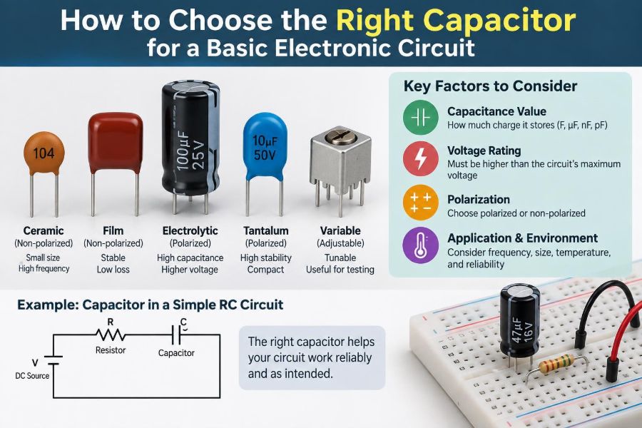
Be careful with markings. A code such as 104 commonly means 100,000 pF, or 100 nF, while 105 means 1 µF. Always confirm the manufacturer’s marking convention when a part is unfamiliar.
🔋 Check the Voltage Rating First
The voltage rating is the maximum continuous voltage the capacitor is designed to withstand under stated conditions. Choose a rating above the highest voltage the capacitor can experience, including normal variation, switching overshoot, and fault conditions that the design reasonably expects.
Using a 6.3 V capacitor on a nominal 5 V rail leaves little margin. A 10 V, 16 V, or higher-rated part may be more appropriate depending on the rail, transients, temperature, and capacitor technology. More voltage margin can improve reliability, but it may increase size and cost.
🌡️ Consider Temperature, Not Just Room Conditions
Capacitor behavior changes with temperature. Electrolytic capacitors can age faster in heat, while some ceramic dielectrics lose substantial capacitance across temperature and applied DC voltage.
Look at the expected ambient temperature and nearby heat sources such as regulators, power transistors, LEDs, and motors. A component rated for a broad temperature range is not automatically required, but a room-temperature assumption can be a weak design choice in an enclosed product.
🧱 Know the Main Capacitor Families
Most basic circuits use ceramic, aluminum electrolytic, tantalum, or film capacitors. Each family solves different problems well, and each has limitations.
- Ceramic: compact, inexpensive, and excellent for high-frequency bypassing.
- Aluminum electrolytic: practical for larger capacitance and bulk energy storage.
- Tantalum: compact with useful capacitance, but sensitive to surge and incorrect application.
- Film: stable and low-loss, often favored for precision analog, AC, and pulse duties.
🟤 Use Ceramic Capacitors for Fast Local Bypassing
Multilayer ceramic capacitors, often called MLCCs, are the usual choice beside digital IC power pins. Their low inductance lets them supply very brief, high-frequency current pulses before noise spreads through the power network.
A 100 nF ceramic placed close to an IC’s power and ground pins is a common starting point. The exact value may vary with the device and application, so use the component manufacturer’s recommendations when they are available.
📉 Watch for Ceramic DC-Bias Derating
Not all ceramics hold their labeled capacitance under working voltage. High-capacitance Class 2 dielectrics, such as X5R and X7R, can lose capacitance when DC voltage is applied; the amount depends on the case size, voltage rating, formulation, and applied voltage.
This matters most when a design depends on a minimum capacitance. A nominal 10 µF ceramic used on a 5 V rail may provide meaningfully less than 10 µF in operation. Check the manufacturer’s capacitance-versus-bias data rather than assuming the printed value is the in-circuit value.
🎯 Distinguish C0G, X7R, and Y5V Ceramics
C0G/NP0 ceramics are highly stable, low-loss parts suited to resonant circuits, precision filters, and timing where capacitance drift matters. Their available capacitance is usually smaller than that of high-value MLCCs.
X7R and X5R are versatile general-purpose choices for decoupling and many filters. Y5V and similar high-permittivity types can provide high nominal values in small packages, but their capacitance can vary greatly with voltage, temperature, and time, making them poor choices for stable timing or precision analog work.
🥫 Choose Electrolytics for Bulk Energy Storage
Aluminum electrolytic capacitors are common after rectifiers, near linear regulators, and on supply rails feeding loads that change more slowly than a ceramic can support alone. Their larger capacitance helps reduce low-frequency ripple and supply voltage sag.
They are usually polarized. Reversing a polarized electrolytic can damage it and may create a safety hazard. Observe the stripe marking, which normally identifies the negative terminal on aluminum electrolytics, and verify the PCB footprint.
🔄 Understand ESR and Why It Matters
Equivalent series resistance, or ESR, models resistive loss inside a real capacitor. When ripple current flows, ESR produces heating and a voltage change proportional to current: V = I × ESR.
Low ESR is often valuable in switching power supplies and pulsed-load circuits. Yet “lowest possible ESR” is not universally correct: some older regulator designs require a certain ESR range for stable control-loop behavior. Read the regulator datasheet instead of substituting capacitor types blindly.
🌊 Account for Ripple Current
Ripple current is alternating current flowing through a capacitor on top of any DC condition. In a power supply, it can heat an electrolytic internally even if the DC rail voltage is safely below its voltage rating.
For capacitors in power paths, inspect the ripple-current specification at the relevant frequency and temperature. A capacitor that is electrically the right size but overheats from ripple may dry out or fail prematurely.
🎵 Use Film Capacitors for Stability and AC Duties
Film capacitors use a plastic film dielectric and are generally non-polarized. They are useful in audio paths, timing circuits, AC filtering, snubbers, and applications where low loss and stable capacitance justify their larger size.
They are rarely the smallest or cheapest way to obtain a high capacitance value. Their strength is predictable behavior, especially where voltage reverses or signal distortion and drift matter.
⚠️ Treat Tantalum Capacitors With Care
Tantalum capacitors can offer substantial capacitance in a compact package, but their application requirements deserve attention. Some types can fail severely when exposed to reverse voltage, excessive surge current, or unsuitable fault conditions.
Use them when their documented properties fit the design and follow the manufacturer’s derating and protection guidance. For many basic low-voltage circuits, ceramic and aluminum electrolytic options are simpler choices.
⏱️ Calculate Timing Capacitors From the Circuit
In an RC circuit, the time constant is τ = RC. After one time constant, a charging capacitor reaches about 63% of its final voltage under an ideal step input. This relationship is useful for delays, pulse shaping, and simple filters.
Suppose a 100 kΩ resistor and 10 µF capacitor are used: the nominal time constant is one second. But resistor tolerance, capacitor tolerance, leakage, temperature drift, and threshold variation can make a real delay noticeably different. For accurate timing, select stable parts and design for tolerances.
🎚️ Select Coupling Capacitors by Low-Frequency Response
A coupling capacitor blocks DC while allowing a changing signal to pass. In an audio circuit, it often works with the next stage’s input resistance to form a high-pass filter.
The cutoff frequency is approximated by fc = 1 / (2πRC). To avoid unwanted bass reduction, choose a cutoff comfortably below the lowest frequency of interest. The relevant resistance is the resistance the capacitor actually sees, which may include bias resistors and input impedance.
🧹 Design Filters With Tolerance in Mind
Capacitors and resistors have manufacturing tolerances. A nominal RC low-pass filter may have a different cutoff frequency from board to board, particularly when using wide-tolerance capacitors.
If the filter only removes obvious switching noise, broad tolerance may be acceptable. If it sets a measurement bandwidth, audio crossover point, or control-loop characteristic, use tighter-tolerance components and calculate the expected range rather than only the nominal result.
🖥️ Decouple Every Digital IC Intentionally
When logic gates switch, ICs draw short bursts of current. Trace inductance makes it difficult for a distant supply capacitor to provide that current quickly. A local bypass capacitor reduces the voltage disturbance at the chip.
- Place a small ceramic capacitor close to each IC supply pin pair.
- Use short, wide connections to power and ground.
- Add bulk capacitance near where power enters a board or where loads change significantly.
- Follow any dedicated decoupling layout guidance for ADCs, RF devices, processors, and switching regulators.
One large capacitor at the board input does not replace local decoupling.
📍 Placement Can Matter More Than a Bigger Value
At high frequencies, a capacitor is not just capacitance. Leads, traces, and vias add inductance. A capacitor placed several centimeters away may be ineffective against a very fast transient, even if its nominal value is large.
Keep high-frequency bypass capacitors physically close to the pins they support. On a PCB, minimize the loop area formed by the supply pin, capacitor, ground return, and associated traces.
🧭 Recognize Parasitics in Real Components
Real capacitors include ESR and equivalent series inductance, or ESL. At sufficiently high frequency, ESL can dominate and the component may behave more like an inductor than an ideal capacitor.
This is why a power system may use several capacitor values and technologies. Small ceramics address fast disturbances, while larger capacitors support lower-frequency load changes. The arrangement should be based on the load and layout, not on an automatic “more values are always better” rule.
🔌 Match the Package to Assembly and Layout
Through-hole capacitors are easy to handle for prototyping and can be mechanically robust. Surface-mount parts save space and suit automated assembly, but their small sizes require careful footprint selection and soldering practice.
Check lead spacing, diameter, height, SMD package code, and polarity marking before ordering. A 10 µF capacitor is not interchangeable with every other 10 µF capacitor if it cannot fit the board or withstand the assembly process.
🛠️ Consider Leaded Breadboards and SMD Prototypes Separately
Breadboards add stray capacitance, resistance, and inductance, and their long jumper wires make high-speed or switching-power experiments less predictable. A capacitor that appears unnecessary on a quiet breadboard can become essential on a compact PCB—or vice versa.
For learning projects, use breadboard-friendly parts while recognizing their limits. For a final design, verify performance on the intended PCB layout rather than treating a breadboard result as the final electrical proof.
🔎 Read the Datasheet Beyond the Headline Value
A distributor listing may show capacitance, voltage, and package, but the datasheet reveals the details that determine suitability. For electrolytics, examine lifetime, ripple-current rating, ESR or impedance, and temperature rating. For MLCCs, examine dielectric type and DC-bias curves.
Also check tolerance, dimensions, recommended land pattern, and any notes about acoustic noise, surge behavior, or operating conditions. Datasheets are not just for advanced designs; they prevent basic substitution errors.
🧪 Measure When the Circuit Is Sensitive
A multimeter with capacitance measurement can identify gross errors, but it may not measure capacitance at the voltage, frequency, or bias condition that matters in the circuit. An LCR meter can provide more useful measurements of capacitance, ESR, and dissipation factor under specified test conditions.
An oscilloscope is often the best troubleshooting tool for power problems. Probe the supply at the IC or load, not only at the regulator output, and use a short ground connection when examining fast noise.
🚫 Avoid Common Selection Mistakes
- Choosing only by capacitance and ignoring voltage rating.
- Using a polarized capacitor where voltage can reverse.
- Assuming every ceramic holds its nominal value under DC bias.
- Putting one bulk capacitor far from every load and calling it decoupling.
- Replacing a specified regulator capacitor with a random available part.
- Using a loose-tolerance electrolytic for a precision timing interval.
- Ignoring ripple current in a switching or rectified power supply.
These errors are common because the circuit may initially seem functional. Problems often emerge under load, temperature changes, startup, or production variation.
🧾 Use a Simple Selection Workflow
- Define the capacitor’s function: decoupling, bulk storage, filtering, coupling, timing, or snubbing.
- Determine nominal capacitance and the minimum capacitance required in operation.
- Find the highest expected voltage and choose practical margin.
- Select a dielectric or technology suited to frequency, stability, polarity, and energy needs.
- Check ESR, ripple current, temperature range, tolerance, and DC-bias behavior as applicable.
- Choose a package that fits the board and supports good placement.
- Verify the design with the relevant datasheet and, where practical, measurement.
🔧 Example: A 5 V Microcontroller Board
A basic 5 V microcontroller board might use a 100 nF X7R ceramic close to each IC power pin pair, following the IC documentation. A larger ceramic or electrolytic near the board’s power entry can help with slower changes in load current.
If a relay, motor, or LED strip shares the supply, the power disturbance may require additional bulk capacitance near that load and proper suppression components. The capacitor values depend on current, wiring, switching behavior, and supply characteristics; there is no universal value that guarantees clean power.
🔊 Example: An Audio Input Coupling Capacitor
Consider a hypothetical audio input with a 10 kΩ input resistance. A 1 µF coupling capacitor gives an approximate cutoff near 16 Hz, while 100 nF gives a cutoff near 160 Hz. The smaller value could noticeably reduce low-frequency content.
For a signal that can swing positive and negative around zero, use a non-polarized capacitor or arrange DC bias so a polarized capacitor always sees the correct polarity. The right choice also depends on source impedance and desired signal quality.
💡 Know When One Capacitor Is Not Enough
Many circuits need a capacitor network because they face disturbances over a range of frequencies. A nearby ceramic handles sharp edges; a bulk capacitor supports longer current demand; a dedicated input or output capacitor may be required for regulator stability.
Do not add parts solely by habit. Each capacitor should have a stated role, and the physical layout should allow it to perform that role.
✅ Make the Final Choice a System Decision
The right capacitor is the part whose actual in-circuit behavior meets the requirement. That means considering capacitance under bias, voltage and temperature limits, losses, frequency response, polarity, physical placement, and the rest of the power or signal path.
Start from function, choose the appropriate technology, confirm the operating limits, and validate the layout. This method is more dependable than copying a value from an unrelated project, and it scales from a simple LED controller to more demanding electronic designs.
Choose a capacitor for the electrical job it must perform in the real circuit—not just for the number printed on its label. With that habit, component selection becomes clearer, troubleshooting becomes faster, and basic circuits become far more reliable. 🔌🧰✨