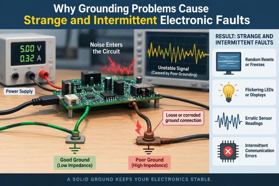

A controller resets when a motor starts. An audio amplifier hums only when a laptop is connected. A sensor reports believable values most of the day, then suddenly jumps when a relay switches.
These faults are frustrating because the circuit may look correct, the software may be sound, and a bench test may pass repeatedly. Replace a component, tighten a connector, move a cable, and the symptom may disappear—temporarily.
Very often, the hidden variable is grounding. Not simply whether a circuit has a ground symbol, but whether every part of the system shares the right reference, has a low-impedance return path, and handles unwanted current without disturbing sensitive signals.
Grounding problems matter in everything from battery-powered embedded boards to industrial control panels. Understanding them turns many “mystery faults” into measurable electrical behavior.
⚡ Ground Is a Reference, Not a Magical Zero-Volt Point
In a schematic, ground is often drawn as one symbol. In real hardware, ground is copper traces, wires, connector pins, chassis metal, solder joints, and sometimes soil. Each has resistance and inductance.
Voltage is always a difference between two points. When current flows through a real ground path, that path develops a voltage drop. Two locations both called “ground” can therefore be at different voltages at the same instant.
Grounding faults arise when a circuit assumes two points are equivalent but current, frequency, or connection resistance makes them electrically different.
🔄 Every Signal Needs a Return Path
A signal conductor does not work alone. Current sent down an output, data line, or supply lead must return to its source through some path.
For a low-frequency signal, the return may follow a wire or ground plane that seems obvious. At higher frequencies, return current tends to take the path with the lowest impedance, often directly beneath the signal trace on a nearby reference plane.
If the intended return route is interrupted, current finds another route: a cable shield, a communication ground, a chassis connection, or stray capacitance. That detour can create noise, emissions, and unpredictable voltage shifts.
📏 Resistance Creates Ground Voltage Drop
The familiar relationship V = I × R explains many faults. A ground lead with only a small resistance can produce a meaningful error when it carries motor, heater, solenoid, or charging current.
Consider a hypothetical board where a sensor ground shares a narrow return trace with a load that changes current by 1 A. Even a 50 milliohm shared path changes the local ground voltage by 50 mV. For a low-level analog measurement, that can be a large error.
The resistance may come from a thin trace, a long wire, oxidation, a loose screw terminal, an undersized connector contact, or a cracked solder joint.
🌊 Inductance Explains Fast, Sharp Disturbances
Resistance is only part of the story. Wires and traces also have inductance, which opposes rapid changes in current. A fast switching current can create a voltage disturbance even if the conductor’s DC resistance is extremely low.
This is why a circuit can measure well with a multimeter and still fail during switching edges. A meter averages slow behavior; it cannot reveal a brief ground bounce that resets a microcontroller.
Long leads, large loop areas, and narrow or interrupted planes increase inductive effects. Fast digital logic, switch-mode power supplies, relays, and motor drives make this especially relevant.
⬆️ What Engineers Mean by Ground Bounce
Ground bounce is a temporary movement of a device’s local ground voltage caused by changing current through shared impedance. The ground has not vanished; its potential has shifted relative to another part of the system.
A microcontroller output may appear to change state at the receiving device even when the transmitter is behaving correctly. The receiver judges the input relative to its own ground, while the sender’s reference may be bouncing.
Inside an integrated circuit, many outputs switching simultaneously can also cause package and bond-wire inductance to move the chip’s local ground reference. Good decoupling and board layout reduce this effect.
🧭 Circuit Ground, Chassis Ground, and Earth Ground Differ
These terms are often used casually, but they serve different purposes. Circuit ground is the signal and power-return reference within electronics. Chassis ground is conductive enclosure metal used for shielding, bonding, and safety arrangements.
Protective earth connects exposed conductive parts to an electrical installation’s safety earth. It is primarily a shock-protection measure, though it can also influence electromagnetic compatibility.
A battery-operated device may have circuit ground without earth ground. A metal-enclosed mains product may have all three. Treating them as automatically identical can create either noise problems or safety hazards.
🪢 Shared Return Impedance Couples Unrelated Circuits
When two loads share part of a return path, one load’s changing current produces a voltage that the other load experiences. This is called common-impedance coupling.
A common example is an LED strip or motor return sharing a PCB trace with an analog sensor return. Dimming or commutation current modulates the sensor’s ground, and the measurement appears noisy even if the sensor itself is stable.
The cure is not always a larger capacitor at the sensor. First, separate the high-current return from the sensitive return and join them at a point or plane region chosen to control shared impedance.
🌟 Star Grounding Is Useful, but Not Universal
Star grounding routes separate returns to a common point. It is often effective in low-frequency analog systems because it prevents load current from flowing through another circuit’s reference lead.
For example, an audio preamplifier, power amplifier, and supply reservoir capacitors may each return to a carefully chosen central node. The physical arrangement matters as much as the diagram.
However, star wiring is not a universal PCB rule. At high frequencies, long radial wires have significant inductance. A continuous ground plane usually provides a better low-impedance return path for fast digital signals.
🧩 Ground Planes Reduce Impedance and Loop Area
A solid ground plane gives return current a wide, short route. It lowers resistance, reduces inductance, and allows high-frequency return currents to stay close to their outgoing signal paths.
Splitting a plane under a fast signal forces its return current to detour. The resulting loop behaves more like an antenna and can degrade signal integrity. A split that looks tidy on a schematic can be harmful on a board.
Use planes thoughtfully: preserve a continuous reference beneath critical traces, place decoupling capacitors close to power pins, and provide nearby return vias when a signal changes layers.
🎛️ Analog Ground and Digital Ground Need Controlled Interaction
Analog circuits may handle microvolt-level sensor signals, while digital circuits create abrupt switching currents. Separating their sensitive areas can be sensible, but the goal is to control return current—not to isolate every ground symbol blindly.
Many mixed-signal IC data sheets recommend a local layout approach based on the converter and its supply pins. The exact connection strategy depends on the IC, converter architecture, frequencies, and board geometry.
For a modest mixed-signal board, a continuous ground plane with deliberate component placement often performs better than a heavily split plane. Keep noisy digital current loops physically away from analog inputs and references.
🎚️ Reference Voltage Errors Can Masquerade as Sensor Faults
An analog-to-digital converter measures an input relative to a reference and ground. If the reference, sensor return, or converter ground moves, the reported value changes even when the physical quantity does not.
Ratiometric sensors can cancel some supply variation when the sensor and converter use the same reference correctly. They do not automatically eliminate errors caused by a shared, noisy ground path.
Symptoms often include readings that change with PWM duty cycle, display activity, radio transmission, or motor operation. Correlating errors with system activity is a valuable diagnostic clue.
🔊 Audio Hum Reveals Ground Loops
A ground loop exists when equipment has more than one conductive ground path, creating a loop that can pick up magnetic fields or carry unwanted current. In audio systems, the result is often hum or buzz.
A desktop computer, mains-powered audio interface, amplifier, and cable television connection can create multiple reference paths through power earths and cable shields. The fault is not necessarily a defective amplifier.
Breaking protective-earth connections is not an acceptable cure. Safer approaches include correctly designed balanced interconnects, audio isolation transformers where appropriate, and equipment grounding arrangements designed for the application.
📡 Cable Shields Are Not Always Signal Returns
A shield’s main job is usually to intercept electric-field noise and, depending on construction and termination, help control radio-frequency currents. It should not automatically be assumed to be a clean signal-return conductor.
Single-ended interfaces often use a signal ground, which can make them vulnerable when devices are far apart. Differential interfaces such as RS-485 or CAN reject some common-mode disturbance, but they still have voltage-range and reference-path requirements.
Shield termination depends on frequency, cable type, enclosure design, and the interface. A rule that works for low-frequency instrumentation may not work for a high-frequency digital cable.
🔌 Connectors and Loose Bonds Create Intermittent Grounds
Intermittent faults frequently originate at the least glamorous locations: connector shells, crimp terminals, mounting screws, cable strain-relief points, and solder joints. Motion, vibration, thermal expansion, and corrosion can alter contact resistance.
A connection may pass a continuity test with almost no current yet fail under load. It can also act like a nonlinear contact, generating noise as vibration changes microscopic contact areas.
Look for symptoms tied to tapping an enclosure, flexing a harness, changing temperature, or operating nearby loads. These patterns are evidence, not proof, but they help narrow the search.
🧪 Why Continuity Tests Can Mislead
A basic continuity tester answers a limited question: is there some electrical path? It usually does not verify that the path remains low resistance under real current, vibration, or switching conditions.
Measure voltage drop across a suspected ground connection while the system is operating. This is often more revealing than measuring resistance with power removed, especially for high-current returns.
For fast disturbances, use an oscilloscope with appropriate probing technique. A long probe ground clip can add a large loop and display ringing that belongs partly to the measurement setup rather than the circuit.
🔍 Measure Ground Relative to the Right Point
“The ground looks noisy” is incomplete unless the measurement points are stated. Probe the voltage between the sensitive device’s ground pin and the power-entry return, or between two grounds that should remain close.
For differential measurements across locations that are not safely tied to the oscilloscope earth reference, use a properly rated differential probe or an isolated measurement method. Incorrect probe grounding can short part of a circuit and create a hazard.
Capture the event that triggers the fault: relay turn-on, motor startup, radio burst, cable movement, or power-state transition. Time correlation gives measurements meaning.
🧷 Decoupling Capacitors Need a Short Current Loop
A decoupling capacitor supplies brief local current when an IC switches, reducing disturbance on the power distribution network. Its effectiveness depends heavily on placement and connection inductance.
Put the capacitor close to the relevant power and ground pins, with short, wide connections into the planes. A capacitor several centimeters away may have adequate capacitance on paper but poor high-frequency behavior in practice.
Decoupling does not replace sound grounding. It limits local transients; it cannot fix a connector return that carries excessive load current or a signal route crossing a plane gap.
⚙️ Switching Loads Stress Ground Systems
Motors, solenoids, relays, valve coils, LEDs driven by PWM, and switch-mode converters create changing currents. Their return paths must be designed as deliberately as their supply paths.
Place flyback suppression, snubbers, or other transient-control components according to the load and switching topology. These parts reduce voltage stress, but their physical connection must keep high-current loops compact.
Do not route a coil’s return through the same narrow section of copper used by a sensor reference. Bring power-load currents back toward their source using a path that avoids sensitive circuitry.
💻 Digital Communication Fails When Common-Mode Limits Are Exceeded
Communication receivers tolerate only a defined range of voltage difference between their local ground and the remote device’s ground. If a ground fault or load current pushes the difference beyond that range, data errors can occur.
Single-ended logic connections are particularly sensitive over long cables. A logic-high level judged against one device’s ground may be invalid at the other device.
Differential signaling improves noise immunity, but it is not magic. Follow the interface requirements for termination, biasing, cable routing, isolation, and any needed reference conductor.
🏭 Industrial Sites Add Powerful Noise Sources
Factories and building-control installations combine long cable runs, variable-speed drives, contactors, motors, welders, and multiple power systems. Ground potential differences can be much larger and more dynamic than on a small bench setup.
Isolation may be appropriate for communications or sensor interfaces crossing noisy boundaries. Isolated power, digital isolators, optocouplers, and isolation amplifiers each have limits involving voltage rating, bandwidth, capacitance, and power delivery.
Protective bonding and installation practices should follow applicable local electrical rules and qualified engineering judgment. Electronics troubleshooting must never compromise personnel safety.
🧱 Enclosures and Mounting Hardware Affect EMC
A metal enclosure can provide a useful high-frequency shield only when its seams, cable entries, and bonds are treated as part of the electromagnetic design. A painted mounting surface may not make a reliable electrical bond.
Cable shields often need a low-impedance connection to the enclosure near the cable entry for high-frequency performance. A long pigtail adds inductance and weakens that connection at high frequencies.
Mechanical details—plating, washers, fastener torque, corrosion resistance, and contact area—can therefore influence electronic behavior. Grounding is partly a mechanical engineering problem.
🛠️ A Practical Troubleshooting Sequence
Start by making the fault repeatable if possible. Note exactly what changes before it happens: load state, cable position, supply source, enclosure state, temperature, or connection to external equipment.
- Draw the actual current paths, including cables, shields, chassis bonds, and power returns.
- Separate high-current switching loads from sensitive analog or logic functions in the drawing.
- Measure DC voltage drop under normal and maximum load conditions.
- Observe suspect ground differences during the triggering event with suitable instruments.
- Temporarily reroute a return, add a short test bond, or power a subsystem independently to test a hypothesis.
- Apply a durable layout, wiring, connector, or bonding correction after identifying the mechanism.
Change one variable at a time. Several simultaneous “fixes” may hide the original cause and make future failures harder to diagnose.
🗺️ Read Schematics as Current-Flow Maps
Schematics emphasize functional connectivity, not physical geometry. A single ground net may conceal several meters of wire, a connector, a chassis bond, and multiple load returns.
During debugging, redraw the relevant portion as a physical map. Mark where current enters and leaves, where sensing occurs, and where a return conductor is shared.
This exercise often reveals the problem before any instrument is connected. If the sensor return and motor return share a terminal or trace segment, the potential coupling mechanism is already visible.
🚫 Common Grounding “Fixes” That Backfire
Some fixes reduce a symptom while creating another problem. Adding random capacitors can shift noise frequencies without fixing the return path. Connecting every available ground point with extra wires can create loops.
- Do not lift protective earth to remove hum; this can create a serious shock hazard.
- Do not split a ground plane beneath fast signals without providing a controlled return path.
- Do not rely on a cable shield alone for a power-return path unless the interface and cable were designed for that purpose.
- Do not assume a thick wire is low impedance at fast edge rates; length and loop area still matter.
- Do not copy a “star ground” pattern into every high-speed design without considering frequency.
📐 Layout Choices That Prevent Faults Early
Good grounding begins before routing. Place switching power stages and loads so their high-current loops are compact. Keep precision amplifiers, references, and sensor connectors away from noisy inductors, clocks, and switching nodes.
Use a solid reference plane where possible. Route sensitive signals over their intended reference, avoid unnecessary layer changes, and provide return vias close to signal vias.
At the system level, allocate connectors and cable routes so noisy power conductors do not travel beside vulnerable analog or high-impedance signal wiring for long distances.
🧠 Frequency Determines the Best Ground Strategy
Ground design is not governed by a single universal topology because different frequencies emphasize different effects. At DC and low frequency, resistance and shared voltage drop may dominate. At high frequency, inductance, loop area, plane continuity, and enclosure bonds become central.
This explains apparently conflicting advice. A star connection can be excellent for a low-frequency audio return, while a plane-based layout is usually better for a fast processor board.
Ask two questions before choosing a strategy: where does the current flow, and how quickly does it change? The answers are more useful than applying a label such as “analog ground” or “clean ground.”
🧯 Safety Grounding Must Remain Separate from Noise Convenience
Noise control and electrical safety interact, but they are not interchangeable goals. Protective grounding exists to provide a safe fault-current path and to keep exposed conductive parts from reaching dangerous voltages under fault conditions.
Any changes to mains-powered equipment, protective earth conductors, insulation barriers, or enclosure bonding should be assessed by qualified people using the requirements applicable to the product and installation.
A quiet system that has lost its protective earth is not a successful repair. Design and troubleshooting choices must preserve safety first.
📋 A Compact Grounding Review Checklist
Before releasing a design or closing a repair, review the system as a set of physical current loops rather than a collection of schematic net names.
| Question | What it helps reveal |
|---|---|
| Where does each load current return? | Shared impedance and overloaded traces or wires |
| Does every critical signal have a nearby return route? | Large loops, emissions, and signal-integrity risk |
| What changes at the instant of failure? | Triggering current and timing correlation |
| Are grounds measured under load and during switching? | Faults invisible to static continuity tests |
| Are chassis, circuit, and protective earth roles defined? | Noise-control confusion and safety mistakes |
✅ The Core Principle Behind Intermittent Ground Faults
Strange faults become understandable when ground is treated as a network with real impedance, physical geometry, and changing current—not as an ideal zero-volt symbol.
A transient reset, drifting measurement, audio buzz, corrupted data packet, or failure that appears when a cable moves may have different symptoms, but each can result from an unintended voltage difference between points assumed to be the same.
The most reliable approach is to identify the current loop, measure the relevant voltage difference during the event, and redesign the path so noisy or high-current returns do not disturb sensitive references.
Good grounding is the deliberate control of return current and reference voltage. Once that idea guides layout, wiring, measurement, and troubleshooting, many intermittent electronic faults stop being mysterious.