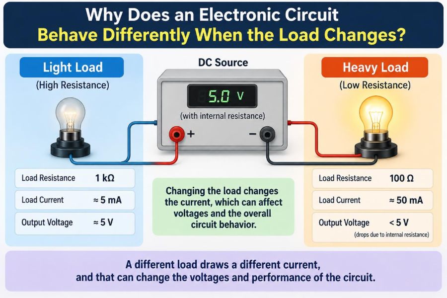

A USB charger may hold a steady 5 V with nothing connected, then its voltage droops when a phone begins charging. An LED that looked perfect on a bench supply may become dim when several more LEDs are added. A motor controller can work during a light test but reset when the motor starts under mechanical load.
These are not necessarily faults in the circuit. They are often the expected result of a basic engineering reality: an electronic source, its wiring, and its control circuits all respond to the current demanded by the load.
“Load” is a simple word, but it covers resistors, lamps, motors, integrated circuits, batteries being charged, speakers, antennas, and entire circuit boards. Each asks the source for voltage, current, or power in a different way.
Understanding load-dependent behavior helps engineers choose components, diagnose failures, predict performance, and avoid treating a no-load measurement as proof that a design will work in service.
🔋 The Load Is What Draws Energy
A load is the part of a circuit that receives electrical energy from a source. In a basic battery-and-resistor circuit, the resistor is the load. In a laptop charger, the laptop is the load.
Loads convert electrical energy into another form: heat in a resistor, light in an LED, motion in a motor, sound in a speaker, or stored chemical energy in a charging battery. Their electrical demand determines much of the circuit’s operating condition.
⚡ A Circuit Is a Complete System
It is tempting to think of a power supply as a fixed-voltage object and the load as something separate. In reality, connecting a load creates a coupled system. The load current flows through the source, cables, connectors, protection devices, and return path.
Every part has some resistance, inductance, capacitance, and practical limit. The voltage actually reaching the load is therefore the result of the entire path, not merely the label printed on the supply.
📐 Ohm’s Law Explains the First Change
For a resistive load, Ohm’s law gives the central relationship: I = V/R. At a fixed voltage, reducing resistance increases current. Increasing resistance decreases current.
If a 12 V source drives a 12 Ω resistor, the ideal current is 1 A. Replacing it with a 6 Ω resistor requests 2 A. That extra current may be acceptable, or it may expose limits that were invisible at 1 A.
🧱 Real Voltage Sources Have Internal Resistance
An ideal voltage source maintains exactly the same voltage at any current. Physical sources do not. Batteries, regulators, generators, transformers, and even a laboratory power supply have some effective internal resistance.
As load current rises, voltage is lost inside the source: Vdrop = I × Rinternal. The terminal voltage becomes lower than the source’s internal generated voltage. This is often called voltage sag or droop.
For example, a hypothetical 5 V source with 0.2 Ω effective internal resistance loses 0.2 V at 1 A. At 2 A, it loses 0.4 V. The load now receives 4.6 V, before cable resistance is considered.
🧵 Wires and Connectors Are Part of the Load Path
A wire is not electrically invisible. Its resistance depends on material, cross-sectional area, length, and temperature. Thin, long wires can cause substantial voltage drop when carrying high current.
Connectors, switch contacts, fuse holders, breadboard springs, and poorly soldered joints add resistance too. A circuit may measure normally at no load because almost no current flows through these weak points. Under load, their voltage drop becomes obvious.
- High-current paths benefit from short, wide conductors.
- Corroded or loose contacts can create intermittent load-dependent faults.
- The return conductor matters just as much as the positive conductor.
🌡️ Heating Can Change the Result Over Time
Many conductors have a positive temperature coefficient: resistance rises as temperature rises. A connection that is merely resistive can heat under load, become more resistive, and drop still more voltage.
This feedback is not always destructive, but it can be. A loose terminal in a high-current path may get hot enough to discolor insulation or damage the connector. Load testing should therefore include time, not only a quick measurement.
💡 Resistance Is Not the Same as a Real Load
Resistors are predictable because their current changes approximately in proportion to voltage. Many useful loads are nonlinear: their current does not follow one constant resistance value.
An incandescent lamp has low resistance when cold and much higher resistance when hot. A diode conducts little below its forward-voltage region, then its current can rise sharply with a small additional voltage. Calling either one “a 10 Ω load” can be misleading.
🔆 LEDs Need Current Control
An LED is a particularly important nonlinear load. Its forward voltage changes with current and temperature, while a small voltage increase can produce a large current increase. Connecting an LED directly to a voltage source without a suitable current-limiting method can damage it.
A series resistor, constant-current driver, or controlled switching circuit sets the current. When the supply voltage changes, the LED current and brightness may change as well, depending on the driver design.
Adding parallel LED branches is not automatically safe. Small differences in forward voltage can make one branch take more current than another unless each branch has appropriate current balancing.
🌀 Motors Behave Differently at Startup
DC motors are dynamic loads. When rotating, a motor generates a back electromotive force, or back EMF, that opposes the applied voltage. This naturally limits current during normal running.
At startup, or if the shaft stalls, back EMF is very low. The motor can then draw a much larger current than its normal running current. A supply that powers a lightly spinning motor may shut down, sag, or overheat when the same motor starts a real mechanical task.
🔊 Speakers and AC Loads Have Impedance
For alternating or changing signals, the useful term is often impedance, not just resistance. Impedance includes resistance plus the effects of capacitance and inductance, and it can vary with frequency.
A loudspeaker’s nominal impedance is a simplified rating, not a fixed resistance at every audio frequency. An amplifier may therefore deliver different current at different frequencies and sound levels. This is one reason amplifier load ratings must be respected.
🧲 Inductors Resist Changes in Current
Inductors, motor windings, relays, and solenoids store energy in a magnetic field. They oppose rapid changes in current. When switched on, current may rise gradually; when switched off, the magnetic field can force the current to continue briefly.
That forced current can create a high voltage spike. A flyback diode across a DC relay coil provides a safe path for current after switch-off, protecting a transistor or other switching device from excessive voltage.
🫙 Capacitors Can Look Like a Short Circuit Initially
A discharged capacitor initially resists a change in voltage, so it can draw a high charging current when connected to a supply. This is called inrush current.
After charging, an ideal capacitor draws no DC current. In a real circuit it has leakage current and equivalent series resistance, but its demand is usually much smaller than during charging. This explains why some supplies trip only at turn-on.
📈 Constant-Power Loads Can Be Counterintuitive
Some converters and electronic devices act approximately as constant-power loads over part of their operating range. If their input voltage falls, they may draw more input current to maintain output power.
Since input power is approximately P = V × I, lower voltage requires higher current for the same power, ignoring losses. Higher current causes additional cable and source voltage drop, which can worsen the original sag.
This behavior is common enough to matter in battery systems and distributed power designs, but it is not universal. A device’s input circuitry and operating limits determine its actual response.
🔌 Power Supply Regulation Has Limits
A regulated supply uses feedback to hold its output near a target voltage as load changes. It measures the output, compares it with a reference, and adjusts its internal switching or pass element.
Regulation has a specified current range, response speed, and stability requirement. Below or above those conditions, the supply may not meet its nominal voltage accurately. A supply label should be read as a set of operating limits, not as a promise of unlimited power.
🛡️ Current Limits and Protection Modes Change Behavior
Many supplies deliberately alter their behavior when current demand is excessive. A bench supply may enter constant-current mode, reducing voltage to hold current at its programmed limit. A USB charger may turn off and retry. A battery protection board may disconnect the output.
These responses can look like mysterious failures until current and voltage are measured together. They are often evidence that a protection function is working, though the selected limit may be unsuitable for the application’s startup surge.
📉 Load Regulation Describes Voltage Change
Load regulation describes how much a supply output changes between light-load and heavy-load conditions. Better regulation means less output-voltage variation across the intended current range.
It should not be confused with line regulation, which describes output change when the input supply changes. Both matter: a converter can behave well with a changing load but poorly when its input battery is nearly discharged.
🧪 No-Load Measurements Can Mislead
A digital multimeter has high input resistance, so it draws very little current. It is excellent for measuring an open-circuit voltage, but that reading does not reveal whether the source can deliver useful current.
A weak battery can show nearly normal voltage with no load and collapse under a lamp or motor. Likewise, a broken wire with a few intact strands may read correctly until current flows. Meaningful diagnosis usually requires a representative load.
🔍 Measure Voltage at the Load, Not Only the Source
When a device misbehaves, measure the voltage directly across its power pins while it is operating. Then measure at the supply output. The difference reveals voltage lost in the distribution path.
For low-voltage systems, even a few hundred millivolts can matter. Microcontrollers, radio modules, and digital sensors may reset or malfunction if their local supply briefly falls below their allowable operating range.
📏 Measure Current Without Changing the Circuit
A multimeter in current mode must be placed in series, and its internal fuse and burden voltage can affect a sensitive circuit. Connecting it across a voltage source in current mode can create a short circuit.
For transient or high-current work, a current shunt resistor plus an oscilloscope, or a suitable current probe, can reveal startup peaks and switching ripple. Select methods appropriate to the expected current and the instrument’s safety rating.
📊 Transients Need an Oscilloscope
A meter often reports an average or slowly updated value. It can miss a 2 ms voltage dip that resets a microcontroller, a brief inrush pulse that triggers protection, or oscillation in a regulator loop.
An oscilloscope captures voltage versus time. Use a short ground connection when probing fast switching nodes; a long ground lead can pick up noise and make the waveform look worse than it is. Probe technique is part of the measurement.
🧭 Ground Bounce Can Masquerade as a Signal Problem
When high current shares a return path with sensitive electronics, voltage develops along that shared path. The local “ground” at one component is no longer exactly the same potential as ground elsewhere. This effect is called ground bounce or common-impedance coupling.
A motor switching current can therefore disturb an analog sensor reading or digital logic threshold even if the regulator output itself appears adequate. Separate high-current and sensitive returns, then join them intentionally near a suitable common point.
🧩 Decoupling Capacitors Supply Brief Local Current
Decoupling capacitors placed near an integrated circuit provide a short, low-inductance path for rapid current changes. They reduce local voltage disturbance while the wider supply network responds.
They are not magic reservoirs. Their effectiveness depends on capacitance, equivalent series resistance, equivalent series inductance, placement, and frequency. A capacitor several centimeters away may be ineffective against a very fast switching demand.
🔁 Parallel Loads Increase Demand
In parallel, each load sees roughly the same supply voltage, while branch currents add. Adding another 12 V lamp branch increases total current demand on the source and shared wiring.
In series, the same current passes through every element and the supply voltage divides between them. A failed open series component stops the whole chain, while a shorted component can increase stress on the remaining parts. The topology changes the consequences of load variation.
🔗 Thevenin Thinking Simplifies Real Sources
A useful model represents a real source as an ideal voltage source in series with a resistance. This is the Thevenin equivalent model. It predicts terminal voltage under different resistive loads without modeling every internal detail.
The model is an approximation, not a complete battery or regulator simulation. It does not fully capture startup behavior, frequency effects, control-loop response, or chemical battery dynamics. Still, it provides valuable first-order intuition.
🧮 A Simple Load-Line View Finds the Operating Point
A source and a nonlinear load each have a voltage-current relationship. Their actual operating point is where both relationships are satisfied at the same time. This graphical method is called a load-line analysis.
It explains why changing a series resistor shifts an LED’s current, or why a transistor circuit settles at one particular collector voltage and current. The circuit does not choose values independently; connected elements constrain one another.
⚠️ Component Ratings Must Cover Normal and Peak Loads
Design from the worst credible operating condition, not only the average current. Consider motor startup, capacitor charging, radio transmit bursts, relay activation, and simultaneous operation of multiple subsystems.
Check voltage rating, current rating, power dissipation, temperature rise, and safe operating limits. A resistor can survive its average power yet fail from repeated pulses; a regulator can meet its current rating yet overheat because it must drop too much voltage.
🌡️ Linear Regulators Turn Voltage Drop into Heat
A linear regulator dissipates approximately (Vin − Vout) × Iout as heat. A load current increase therefore raises regulator temperature directly, especially when the input-to-output voltage difference is large.
This is why a circuit that works at 100 mA may become too hot at 800 mA without changing any voltage setting. A switching regulator is often more efficient for large voltage conversion, but it introduces its own ripple, layout, and electromagnetic-noise considerations.
🛠️ A Practical Troubleshooting Sequence
Start by identifying when the change occurs: at connection, startup, sustained operation, a temperature change, or a particular mode. Then compare the load’s expected current with the source and wiring capability.
- Measure supply voltage with no load and with the fault-producing load connected.
- Measure voltage at both the source terminals and the load terminals.
- Check current, including startup current if possible.
- Inspect connectors, solder joints, cables, fuses, and return paths for resistance or heating.
- Use a known safe test load to isolate whether the source or the device is responsible.
- Check protection modes and thermal behavior before replacing components.
Never bypass a fuse, current limiter, or protection circuit merely to “see if it works.” That can convert a diagnostic question into component damage or a fire hazard.
🚫 Common Mistakes When Testing Loads
- Assuming the printed supply voltage is present at the device. Measure it at the load terminals.
- Using a breadboard for high current. Its contacts and jumpers are not intended for every power application.
- Ignoring return-path resistance. Current must complete a loop.
- Choosing a supply only by steady-state current. Surge demand may dominate.
- Adding a larger fuse to stop nuisance blowing. The wiring and components may no longer be protected.
- Using one measurement as final proof. Load, time, temperature, and waveform can all change the answer.
🧰 Design Choices That Improve Load Tolerance
Good design reduces unwanted interaction between load changes and circuit behavior. Use conductors sized for current and length, connectors rated for the environment, and a supply with adequate continuous and transient capability.
Place decoupling capacitors close to active devices, isolate noisy loads where needed, and use separate or carefully routed returns for power electronics and precision signals. Add soft-start or inrush limiting when capacitors or motors would otherwise demand an excessive surge.
Simulation and spreadsheet calculations help early, but a prototype must still be tested with representative loads. Real cable lengths, temperature, mechanical connections, and load waveforms often determine the final result.
✅ The Core Principle: Load Changes Reveal the Whole Circuit
A circuit behaves differently when the load changes because current, voltage, power, temperature, and control feedback are interconnected. More current makes unavoidable resistances and limits more visible. Dynamic loads also introduce startup surges, frequency effects, stored energy, and fast transients.
The useful question is not simply, “Why did the voltage change?” Ask where current flows, what voltage is lost along the path, whether the source is regulating or limiting, and how the load’s own characteristics change with voltage, time, and temperature.
Once a circuit is viewed as a source, interconnects, controls, and load operating together, many apparently unpredictable problems become measurable and understandable.
An electronic circuit does not operate independently of its load; the load is one of the conditions that defines its operating point. Measure under realistic conditions, design for peaks as well as averages, and treat every conductor in the current path as part of the circuit. 🔌📏⚡