
You are on a video call in one room, then walk toward the far end of a building. The picture freezes, the audio breaks into fragments, and eventually the connection disappears. It is tempting to ask a simple question: “How far does Wi-Fi reach?”
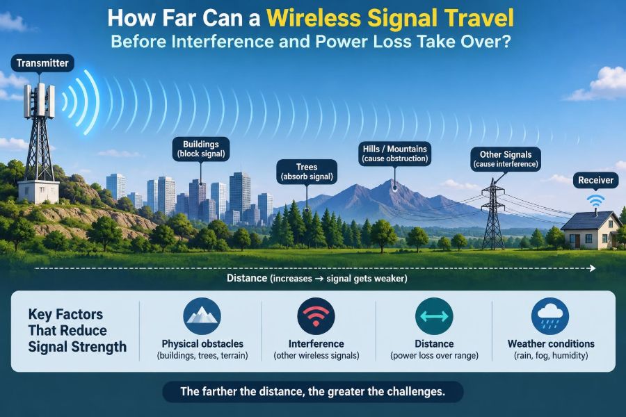
Engineers know that the answer is rarely a single distance. A wireless signal does not hit an invisible wall at a fixed number of metres. It gradually weakens, competes with noise, bounces from surfaces, and may be blocked or distorted by the environment around it.
The same principle applies to Bluetooth earbuds, cellular phones, satellite links, garage-door remotes, industrial sensors, and long-range Internet-of-Things devices. Each is a radio system making trade-offs among power, frequency, antenna design, data rate, bandwidth, and reliability.
Understanding those trade-offs turns “wireless range” from a vague product claim into an engineering problem that can be estimated, measured, and improved.
📡 Wireless Range Is Not One Fixed Distance
A transmitter can often be detected farther away than it can deliver useful data. This distinction is the reason range specifications can be misleading when read without context.
At a certain distance, a receiver may still recognize that radio energy exists, but the signal may be too weak or too corrupted to decode a message reliably. Another device may maintain a slow sensor link there while a high-definition video stream fails completely.
Useful range is the distance at which the required service still meets its reliability and data-rate target. That target differs sharply between applications.
🔊 Think of Radio Like a Conversation
A useful analogy is a conversation across a noisy room. Your voice becomes quieter as your listener moves away, while other conversations and background music make it harder to understand each word.
Radio behaves similarly, except that walls, metal objects, reflections, antenna direction, and electronic noise all affect what arrives. Raising your voice is like increasing transmit power, but it is only one possible improvement.
A better microphone, a quieter room, clearer speech, or a slower speaking rate can also help. In a wireless system, those correspond to antenna gain, reduced interference, robust modulation, and lower data rate.
📉 The Fundamental Problem: Path Loss
Path loss is the reduction in radio signal power as an electromagnetic wave travels from transmitter to receiver. Even in completely open space, energy spreads over an ever-larger area as the wave expands outward.
This does not mean the energy vanishes. Rather, only a smaller fraction of it is captured by a receiver antenna at greater distance. The received power therefore falls rapidly as separation increases.
In ideal free space, doubling the distance reduces received power by about 6 dB. A 6 dB reduction means the received power is roughly one quarter of its earlier value, not merely half.
📏 Why Engineers Use Decibels
Wireless link calculations commonly use decibels (dB), a logarithmic unit that makes large power ratios easier to add and subtract. Power levels are often expressed in dBm, meaning decibels relative to 1 milliwatt.
For example, a receiver sensitivity of −90 dBm describes a much weaker signal than −60 dBm. The more negative value is lower power, but a receiver capable of decoding it is more sensitive.
Decibels simplify a link budget: transmitter power and antenna gains are added, while cable loss, propagation loss, and obstacles are subtracted.
🧮 The Free-Space Path-Loss Starting Point
For a clear, unobstructed path, engineers often begin with the free-space path-loss model. With distance in kilometres and frequency in megahertz, a common form is:
FSPL (dB) = 32.44 + 20 log10(distance) + 20 log10(frequency)This is a planning tool, not a promise. It assumes line of sight, no reflections, no walls, and conditions unlike most homes, offices, factories, or city streets.
Its main lesson is powerful: path loss rises with both distance and frequency. Higher-frequency systems generally need more careful planning to achieve the same coverage.
📶 Frequency Changes the Coverage Challenge
Lower-frequency signals generally travel farther for a given link budget and tend to penetrate many materials more effectively. This is one reason cellular coverage at lower bands can reach broad rural areas, while higher bands are useful for dense capacity in smaller areas.
At 2.4 GHz, Wi-Fi and Bluetooth often travel farther through a building than 5 GHz Wi-Fi. At 5 GHz and 6 GHz, more spectrum may be available, but walls and distance usually impose a stronger practical penalty.
This is a tendency, not a universal law. Antennas, legal power limits, channel width, building materials, and receiver quality can outweigh a simple frequency comparison.
🧱 Walls Are Not Just Extra Distance
A wall changes a radio path in ways that open-air distance does not. Drywall may cause a moderate reduction, while reinforced concrete, brick, foil-backed insulation, tinted low-emissivity glass, and dense masonry can create much larger losses.
Material thickness, moisture content, angle of incidence, and embedded metal all matter. A signal passing straight through a wall may behave very differently from one crossing it at a shallow angle.
Two homes with the same floor area can therefore have radically different Wi-Fi coverage. Floor plans alone cannot accurately predict performance.
🚪 Doors, People, and Moving Obstacles
Wireless channels are dynamic. A closed fire door, a delivery cart in a warehouse aisle, or a crowd of people between two devices can noticeably change the received signal.
Human bodies contain water and can absorb or attenuate microwave-frequency energy. This helps explain why a wearable or phone connection can change when a person turns, pockets a device, or places their hand over an antenna.
For a critical installation, test the system under normal operating conditions rather than in an empty room on a quiet weekend.
🪞 Reflections Create Multipath
Radio waves reflect from metal, walls, floors, ceilings, vehicles, and large equipment. The receiver may therefore receive multiple copies of the same transmission, each arriving after a slightly different path and delay.
This is called multipath propagation. Sometimes reflected signals reinforce one another; at other locations they partially cancel, producing a deep fade even when transmitter and receiver are not very far apart.
A small movement can matter. Shifting a laptop, antenna, or access point by a fraction of a wavelength can change the pattern of constructive and destructive interference.
🌊 Fading Explains Sudden Signal Dips
Fading is the variation in received signal strength over time, position, or frequency. It is why a connection can be excellent at one desk and unreliable a step away.
Fast changes can occur when people or objects move through a multipath environment. Slower changes may result from weather, foliage, seasonal changes, or machinery being moved around a site.
Engineers design with a fade margin: extra link-budget headroom beyond the minimum theoretical requirement. Margin helps a link survive ordinary variation instead of operating on the edge of failure.
🔇 Noise Sets a Receiver’s Floor
A receiver cannot hear arbitrarily weak signals because every electronic system has noise. Thermal noise arises from the random motion of charge carriers, while receiver circuits add their own noise.
Noise is often considered across the channel bandwidth. A wider channel collects more noise energy than a narrower one, all else being equal.
The relevant question is not simply “How strong is the signal?” It is “How strong is the signal compared with the noise in the receiving system?”
⚖️ Signal-to-Noise Ratio Determines Clarity
Signal-to-noise ratio, or SNR, compares wanted signal power with background noise. A higher SNR usually allows the receiver to decode data more reliably and to use faster, more efficient transmission methods.
A low SNR may still support a simple, slow message, while a demanding link carrying video may need substantially better conditions. This is why usable range shrinks as a system is asked to deliver more throughput.
Signal bars alone are incomplete diagnostics. A fairly strong signal in a noisy channel can perform worse than a weaker signal in a clean one.
🚦 Interference Is Not the Same as Noise
Noise is broadly random unwanted energy. Interference is usually a distinct transmission or electronic source that overlaps the wanted signal in frequency, time, or both.
Nearby Wi-Fi networks on the same or overlapping channels, Bluetooth activity, cordless devices, microwave ovens, wireless cameras, and poorly shielded electronics can all affect certain bands. In licensed systems, interference may instead come from other planned users, adjacent channels, or equipment faults.
Interference can be intermittent, which makes it particularly frustrating. A network may look healthy during a brief test yet fail during busy periods.
🧭 Co-Channel Contention Limits Real Capacity
When multiple Wi-Fi devices use the same channel, they do not always behave like uncontrolled noise sources. Wi-Fi devices can often detect one another and take turns transmitting using a contention method.
That coordination can avoid some collisions, but it also means the channel’s airtime is shared. A distant client transmitting slowly may occupy more airtime for each packet, reducing capacity for everyone on that channel.
Coverage and capacity are therefore related but different goals. A network can reach an area while still being too congested to serve it well.
🙈 The Hidden-Node Problem
A hidden node occurs when two wireless clients can both reach an access point but cannot hear each other. Each may decide the channel is idle and transmit at the same time.
The access point then receives overlapping packets, increasing retries and reducing effective throughput. Large buildings, outdoor areas, and sparse deployments can create these conditions.
More transmit power is not always the answer. It can make clients audible at greater distances without ensuring that the clients can sense one another, and it may worsen channel sharing.
📦 Data Rate Has a Range Cost
High data rates generally require a cleaner received signal. They may use denser modulation—packing more bits into each symbol—and often wider channels, both of which demand better signal conditions.
Modern systems adapt their modulation and coding rate automatically. As conditions worsen, they select more robust modes that carry fewer bits per second but are easier to decode.
This produces a familiar pattern: a connection may remain connected at long range while browsing becomes slow and video calls become unreliable. The radio link is adapting, not necessarily failing outright.
🛡️ Coding Trades Throughput for Reliability
Error-correcting codes add structured extra information to a transmission. With enough correctly received data, the receiver can sometimes reconstruct bits affected by noise or interference.
Coding improves resilience, but it consumes airtime or reduces the net user data rate. Retransmissions add another layer of protection, though repeated retries eventually make a link inefficient.
For a small temperature sensor sending brief readings, a slow robust mode may be ideal. For a real-time control loop or video link, latency and packet loss may matter as much as average throughput.
📐 Antenna Gain Focuses Energy
An antenna does not create energy. Antenna gain describes how effectively it concentrates radiation in one direction compared with an ideal reference antenna.
An omnidirectional antenna spreads coverage around itself, usually with less reach in any one direction. A directional panel, Yagi, dish, or parabolic antenna focuses energy into a narrower beam, improving a point-to-point link.
That focus must be aimed correctly. A high-gain antenna can be an excellent solution for two fixed buildings and a poor choice for serving users scattered around a room.
↔️ Polarization and Alignment Matter
Radio antennas have polarization, commonly vertical, horizontal, circular, or a combination. A substantial polarization mismatch between transmitting and receiving antennas can reduce received power.
At short range, a strong signal may hide this problem. Near the edge of coverage, simply rotating an antenna or matching orientations can restore a marginal link.
Portable devices complicate the issue because their orientation constantly changes. Many modern systems use multiple antenna elements to reduce sensitivity to one particular position.
🧩 MIMO Uses Multiple Paths Constructively
MIMO, short for multiple-input multiple-output, uses multiple transmit and receive antennas. In favourable conditions, it can send separate spatial streams, improve reliability through diversity, or do both depending on the system.
Multipath, once treated only as a problem, can provide the distinct paths MIMO needs. This is one reason modern Wi-Fi can perform surprisingly well in reflective indoor spaces.
MIMO is not magic range multiplication. It depends on antenna spacing, channel conditions, device capability, and the access point’s ability to communicate with many clients.
📡 Transmit Power Has Legal and Practical Limits
Increasing transmit power can improve the downlink, but wireless communication is usually two-way. If an access point can shout farther than a phone or sensor can reply, the overall connection remains limited by the weaker return path.
Regulations also limit power and, in some cases, effective isotropic radiated power (EIRP), which accounts for antenna gain. Limits vary by country, frequency band, channel, and application.
High power can also increase interference to other users. Good design seeks the lowest power that delivers dependable coverage, not the highest setting available.
🔋 Battery-Powered Devices Face a Different Trade-Off
A battery sensor may deliberately transmit briefly and infrequently to preserve energy. Its design may prioritize sensitivity, coding, and low duty cycle over high throughput.
Protocols intended for low-power wide-area communication can achieve long links by using narrow bandwidths, low data rates, and receiver techniques that work near the noise floor. The compromise is limited payload size, longer airtime, or lower responsiveness.
There is no free long-range, high-speed, tiny-battery solution. The physics and energy budget must be balanced against the application’s actual needs.
🌧️ Outdoor Range Adds Terrain and Weather
Outdoor links can benefit from fewer walls, but terrain, buildings, trees, and the curvature of the Earth become significant over longer distances. A clear visual path is helpful, yet the zone around that path also matters.
At microwave frequencies, heavy rain, wet foliage, and atmospheric conditions can add attenuation, especially on higher-frequency links. The impact depends on frequency, path length, rainfall intensity, and the fade margin available.
Outdoor antenna systems also need suitable mounting, grounding, surge protection, weatherproof connectors, and regulatory compliance. A good radio link can still fail because its installation hardware degrades.
🔍 The Fresnel Zone Is More Than Line of Sight
For a point-to-point outdoor link, it is not enough for antennas to merely see each other. The region around the direct path, called the Fresnel zone, should be substantially clear to avoid destructive diffraction and reflection effects.
Objects such as tree branches, roof edges, or terrain ridges intruding into this zone can weaken a link even when the direct visual line seems unobstructed. The zone is wider near the middle of the path.
This explains why raising an antenna by a modest amount can produce a dramatic improvement. The elevation may clear a critical obstruction rather than simply reduce distance loss.
🏢 Indoor Wi-Fi Needs a Site-Specific Design
An access point placed centrally in a home may be adequate, but large offices, schools, hospitals, and factories require a more deliberate approach. Construction materials, client density, roaming needs, and interference sources all influence the design.
Access points should usually be positioned where users need service, not hidden in a wiring closet or installed solely where cabling is convenient. Ceiling placement may be effective in open areas, but surrounding materials and antenna patterns still matter.
A predictive survey can guide placement, while an on-site survey validates what the real environment does to radio coverage.
🧪 Measure More Than Signal Strength
A received-signal-strength indicator, or RSSI, is useful but incomplete. A proper assessment also considers SNR, noise level, retransmission rate, channel utilization, roaming behaviour, latency, packet loss, and application performance.
For example, a barcode scanner network may tolerate modest throughput but require rapid, reliable roaming. A lecture hall may need high aggregate capacity. An industrial sensor network may need delivery assurance over raw speed.
Define pass criteria before testing. “The device connects” is not a sufficient criterion when the real requirement is continuous voice, stable control, or predictable data collection.
🛠️ A Practical Method for Troubleshooting Range
When a link becomes unreliable, avoid changing every setting at once. Work from evidence toward the most likely limiting factor.
- Confirm the symptom: disconnections, low throughput, high latency, or one-way communication.
- Check both directions of the link; weak client transmit power is a common limitation.
- Measure RSSI, SNR, retry rate, and channel use where the problem occurs.
- Look for physical changes: walls, doors, antenna position, machinery, foliage, or newly installed equipment.
- Test another channel or band where appropriate to separate interference from basic path loss.
- Improve placement, antenna selection, or access-point density before raising power indiscriminately.
Documenting test locations and conditions makes intermittent problems easier to compare over time.
⚠️ Common Range-Extension Mistakes
Several intuitive fixes create new problems. Repeater placement is a classic example: a repeater located where the original signal is already poor has little quality to repeat.
- Installing an extender in a dead zone: place it where it still has a strong backhaul connection.
- Maxing out transmit power: this can increase interference and create asymmetric links.
- Using one crowded channel everywhere: overlapping coverage needs a channel plan, not just more radios.
- Ignoring wired backhaul: an Ethernet-connected access point often outperforms a wireless repeater.
- Trusting a single speed test: test at busy times and at multiple locations.
The best correction depends on whether the real bottleneck is path loss, interference, congestion, backhaul, or client hardware.
🗺️ Choosing the Right Technology for the Distance
Different wireless technologies are optimized for different jobs. Wi-Fi emphasizes local high-speed networking; Bluetooth supports short-range peripherals; cellular systems provide managed wide-area mobility; directional microwave links connect fixed locations; low-power wide-area systems prioritize sparse, small data messages.
| Need | Typical design priority | Useful approach |
|---|---|---|
| Home or office data | High throughput and indoor coverage | Well-placed Wi-Fi access points with wired backhaul |
| Two fixed sites | Focused long-distance connection | Aligned directional antennas and a clear Fresnel zone |
| Battery sensor | Low energy and occasional data | Low-power, low-data-rate radio design |
| Mobile wide-area service | Coverage and roaming | Cellular or another managed wide-area network |
Selecting technology after defining payload, latency, power, mobility, and reliability requirements prevents expensive attempts to force one system into the wrong role.
🧠 The Core Principle: Link Budget, Not a Magic Number
The distance a wireless signal can travel is determined by the entire link budget: transmit power, antenna gain, cable losses, path loss, walls and terrain, interference, receiver sensitivity, required data rate, and the margin needed for changing conditions.
A link fails when the receiver can no longer distinguish the required information with sufficient reliability—not simply when a radio wave stops existing. That failure point moves when the channel, environment, equipment, or service requirement changes.
The practical engineering question is therefore not “What is the maximum range?” but “What range can this specific system support, at this data rate and reliability, in this environment?”
Wireless range is the outcome of a complete radio system and its surroundings, so dependable coverage comes from balanced design and measurement rather than a single advertised distance. When the link budget is understood, interference and power loss become manageable design constraints instead of mysterious failures. 📡🔧