
A board powers up, an indicator LED glows, and yet the product does not work. A motor controller refuses to start. A sensor output looks stuck. A digital interface has the correct supply rail but will not communicate.
These are familiar faults because electronic circuits often fail in ways that are not visible. A burnt component is easy to spot; a cracked solder joint, missing enable signal, excessive ripple, or timing error is not.
The most efficient troubleshooting does not begin by replacing parts at random. It begins by asking what electrical condition should exist at each stage, then measuring whether that condition is actually present.
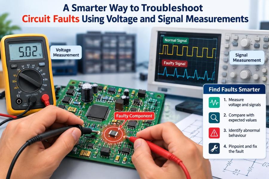
Voltage measurements reveal the circuit’s operating conditions. Signal measurements reveal its activity and timing. Used together, they turn troubleshooting from guesswork into a structured process of narrowing down evidence.
🧭 Start With a Fault Model, Not a Suspect Component
A circuit fault is a mismatch between expected behavior and observed behavior. Before picking up a probe, describe that mismatch plainly: “The 5 V rail exists, but the microcontroller never leaves reset,” or “The amplifier has input audio but no speaker output.”
This statement becomes a fault model: a working hypothesis about where normal operation stops. It prevents a common mistake—testing many unrelated points simply because they are convenient to reach.
Think in functional blocks: input power, regulation, control, sensing, processing, and output. A fault generally appears at the boundary where one block no longer supplies the condition required by the next.
🗺️ Read the Schematic as a Map of Expectations
A schematic is more than a wiring diagram. It shows intended current paths, reference voltages, logic states, bias networks, and signal flow. Use it to predict what a measurement should look like before making it.
For each relevant node, identify whether it should be:
- a fixed DC voltage,
- a changing analog voltage,
- a digital high or low state,
- a pulse train or data waveform, or
- normally disconnected until a switch or controller enables it.
Datasheets, board silkscreen labels, and known-good units can refine these expectations. A nominal value is useful, but its meaning depends on the circuit. A 1.2 V reading may be correct at a reference pin and alarming at a 3.3 V supply rail.
🔒 Make the Measurement Safe Before Making It Useful
Measurements can damage equipment or create hazardous conditions when the instrument, probe, and circuit are mismatched. Start by confirming the power source, voltage range, grounding arrangement, and accessible test points.
Bench oscilloscopes usually connect their probe ground clips to protective earth through the mains lead. Attaching that ground clip to a non-grounded point in a mains-referenced or high-side circuit can create a short circuit. Use an appropriate isolated measurement method, differential probe, or battery-powered instrument where the design requires it.
Disconnect power before resistance or continuity tests. Discharge capacitors where stored energy is possible, and avoid working alone around potentially dangerous voltages. Safety is not separate from diagnosis; an unsafe setup can produce misleading readings as well as damage.
🔧 Choose the Instrument That Answers the Question
A digital multimeter (DMM) is excellent for DC levels, resistance, continuity, diode checks, and many low-frequency values. It is often the first tool to use because it is quick, robust, and easy to interpret.
An oscilloscope shows voltage changing over time. It reveals ripple, noise, switching edges, intermittent dropouts, pulse width, ringing, and communication activity that a DMM may average into an apparently normal number.
Other tools can be valuable, but only when they answer a specific question:
- Logic analyzer: captures multiple digital channels and decodes protocols.
- Current probe or shunt measurement: exposes abnormal loading and startup behavior.
- LCR meter: checks inductance, capacitance, and resistance, usually out of circuit.
- Thermal camera: helps locate unusual heating, but does not identify every electrical cause.
📏 Understand What a Voltage Reading Really Means
Voltage is a difference in electrical potential between two points. A meter display does not report an absolute property of one pin; it reports the difference between the red probe and the black reference probe.
Most board-level DC checks use circuit ground as the reference. That works well only if the chosen ground is genuinely the local reference for the part of the circuit being tested. Isolated converters, current-sense circuits, and floating interfaces may require a different reference strategy.
Always record both the measured node and the reference point. “Pin 3 is 2.8 V” is incomplete. “Pin 3 is 2.8 V relative to local analog ground” is a result another technician can reproduce.
⚡ Verify Power at the Load, Not Just at the Source
Finding the correct voltage at a connector or regulator output is encouraging, but it does not prove that every downstream device receives it. A damaged trace, fuse, ferrite bead, connector, switch, or solder joint can isolate the load.
Measure close to the IC or module that is malfunctioning. Compare its supply pin voltage with the upstream source, preferably while the circuit is attempting to operate. A rail can look healthy with no load and collapse when a device starts drawing current.
For example, a nominal 3.3 V regulator might measure correctly at its output pad, while the microcontroller supply pin reads much lower because a corroded via or cracked connection is dropping voltage under load.
🌊 Look Beyond DC: Ripple, Noise, and Brief Dips
A DMM may report a stable average even when a supply contains disruptive ripple or short voltage dips. Digital logic can reset, analog stages can distort, and converters can misbehave despite a meter reading that appears close to nominal.
Use an oscilloscope with a short ground connection to inspect supply rails. Long probe ground leads form a loop that can pick up switching noise and exaggerate high-frequency artifacts. A ground spring or very short connection usually gives a more trustworthy view.
Evaluate ripple in context. Switching regulators naturally produce some periodic ripple, while a sensitive reference or analog front end may require much cleaner behavior. The useful question is not “Is there any noise?” but “Is the observed noise consistent with this rail’s function and the component’s limits?”
🪫 Test the Power Path Under Real Operating Conditions
Power faults often appear only during startup, transmission, motor movement, relay actuation, or another high-current event. A static voltage check can therefore miss the most important moment.
Observe the rail while reproducing the failure. If possible, trigger the oscilloscope from an enable signal, a button press, or another event that precedes the fault. This shows whether voltage droop occurs before or after the circuit stops working.
A brief dip may point to excessive load current, insufficient input capacitance, a weak source, poor connector contact, or a regulator entering current limit. It does not automatically identify which one, but it sharply narrows the next investigation.
🧱 Check Ground Integrity as Carefully as Supply Integrity
Ground is a circuit path, not a magical zero-volt destination. Current flowing through traces, wires, connectors, and solder joints creates small voltage drops. In sensitive circuits, those drops can alter measurements and operating thresholds.
Measure voltage between ground points while the system is active, especially between a high-current load return and a controller or sensor ground. A significant or changing difference can indicate ground-path resistance, poor layout, damaged connections, or current returning through an unintended route.
Ground problems can imitate many other faults: erratic digital inputs, offset analog readings, communication errors, and random resets. When symptoms are intermittent or load-dependent, ground deserves early attention.
🧮 Use Resistance Measurements With the Power Off
Resistance checks are valuable for locating opens and shorts, but they must be interpreted carefully. With power removed, measure continuity across fuses, traces, jumpers, switches, and suspected solder joints.
A very low resistance from a supply rail to ground can suggest a short, but low resistance is not always abnormal. Large ICs, motors, inductors, and charged capacitors can make simple readings ambiguous. Compare with a known-good board when available, or isolate sections of the circuit.
Do not assume that a continuity beep proves a connection is good under operating current. A marginal joint may pass a meter’s tiny test current and still develop an unacceptable voltage drop when the circuit is loaded.
🧲 Use Diode Mode to Find Semiconductor Clues
Diode-test mode applies a small test current and displays an approximate forward voltage response. It can quickly identify many shorted protection diodes, transistor junctions, rectifiers, and damaged IC pins when used with power removed.
Expected readings depend on the component and surrounding circuit. Parallel paths often affect the result, so diode mode is better treated as a comparative diagnostic tool than as a complete component specification test.
Probe the same rail or interface pins on a working and faulty board, using the same polarity. A conspicuously different reading can identify a suspicious branch without immediately removing components.
🧠 Separate “No Signal” From “Signal Not Recognized”
When an output does not respond, first determine whether the driving signal is absent or merely ineffective. These are different faults with different likely causes.
For a digital control line, check whether the intended logic transition reaches the receiving pin. If it does not, trace backward through the driver, pull-up network, connector, and upstream controller. If it does reach the pin, investigate supply levels, thresholds, reset state, configuration, loading, or the receiving device itself.
This distinction avoids replacing a controller when the actual problem is a broken trace, and avoids blaming a connector when a valid waveform is reaching a device that cannot use it.
📈 Learn the Basic Shape of Healthy Digital Signals
A digital signal is not only “high” or “low.” Its waveform has amplitude, rise time, fall time, timing, duty cycle, overshoot, undershoot, and noise margin. These details matter more as edge speed and data rate increase.
A healthy logic waveform generally reaches valid voltage levels cleanly enough for the receiving device, remains stable during its intended bit period, and transitions at the correct times. Its exact appearance depends on logic family, voltage domain, termination, trace length, and probe loading.
For example, a line that rises slowly may work at room temperature but fail with a different load or supply level. A scope exposes that weakness; a meter may simply display an average voltage around the middle of the rail.
🕰️ Measure Timing, Not Just Amplitude
Many circuits fail even though every signal eventually reaches the correct voltage. A reset pulse may be too short, a clock may start too late, a chip-select signal may overlap incorrectly, or a converter’s feedback loop may respond too slowly to load changes.
Use cursors or automatic scope measurements to compare period, frequency, pulse width, and delay between signals. Treat instrument measurements as aids rather than unquestioned truth; verify trigger stability and timebase settings when results appear surprising.
Timing analysis is especially useful around resets, enables, clocks, PWM outputs, and serial interfaces. In these systems, when a voltage changes can be just as important as how far it changes.
🧷 Probe Without Creating a New Fault
Every probe interacts with the circuit. A typical oscilloscope probe adds capacitance, which can slow a high-impedance or high-speed node. A poorly placed ground lead can add inductance and show ringing that is mostly created by the measurement setup.
Use the correct probe attenuation setting and ensure the scope channel matches it. Compensate passive probes using the oscilloscope’s calibration output before detailed work. Incorrect compensation distorts square waves and can lead to false conclusions.
For delicate or fast nodes, consider active probes, low-capacitance probes, or dedicated test points. If the waveform changes dramatically when the probe touches it, that interaction is itself useful evidence: the node may be weakly driven or unusually sensitive to capacitance.
🎚️ Check Bias Voltages in Analog Stages
Analog circuits frequently depend on bias: carefully established DC operating points that let transistors, op-amps, and amplifiers process signals in their intended linear region. When bias is wrong, a signal can be present but clipped, distorted, or blocked.
Compare DC voltages at transistor terminals or op-amp inputs and outputs with schematic expectations. In a single-supply audio circuit, an amplifier output may sit near a midpoint reference at idle rather than at 0 V. Calling that midpoint a fault would be a misunderstanding of the design.
A missing reference, leaky capacitor, failed resistor, or incorrect feedback path can shift bias. Signal tracing becomes much more meaningful once the stage’s DC conditions are known to be plausible.
🔊 Trace an Analog Signal Stage by Stage
For analog faults, inject or use a known input signal and follow it through each block: input connector, coupling network, gain stage, filter, driver, and output. At every point, observe both DC bias and AC waveform.
A hypothetical audio preamplifier may show a clean sine wave at its input, a clipped waveform after the first transistor, and silence at the output. The first abnormal node is usually more informative than the final symptom.
Keep injection levels modest. An excessively large test signal can force a healthy stage into clipping and create a false fault. Match the test frequency and amplitude to the function being evaluated whenever practical.
🔁 Diagnose Feedback Loops With Care
Regulators, amplifiers, motor controllers, and control systems often use feedback: they measure an output and adjust drive to keep that output near a target. A fault in the feedback path can make the system oscillate, saturate, shut down, or regulate at the wrong value.
Measure the reference, the sensed feedback node, and the output together when possible. If the reference is stable but the feedback node is incorrect, investigate the divider, sensor, compensation network, and connections between them.
Do not casually alter feedback components during live testing. Loop stability depends on component values, parasitic effects, and load conditions. A temporary modification can make diagnosis harder or stress the circuit.
🔄 Recognize Switching Power Supply Signatures
Switch-mode supplies convert energy in pulses, so their waveforms are inherently dynamic. Inductor current, switch-node voltage, gate drive, output ripple, and feedback response all carry diagnostic information.
A missing output may result from no input power, an inactive enable pin, undervoltage lockout, overcurrent protection, thermal shutdown, a damaged switch, or a faulted load. Measuring only the output does not distinguish these possibilities.
Start with input voltage and enable state, then inspect output behavior and, where safe and appropriate, controller drive signals. High-voltage switching nodes require suitable probes, bandwidth, grounding practice, and safety precautions; do not use ordinary probing methods beyond their ratings.
💬 Decode Communication Problems in Layers
Serial buses such as UART, I²C, SPI, CAN, and differential links fail for reasons that include missing power, wrong voltage levels, absent pull-ups, poor termination, reversed wiring, timing errors, and incompatible configuration.
Begin with physical electrical conditions. Is the bus powered? Are idle levels plausible? Is there activity when communication should occur? Only then move toward protocol decoding and software configuration.
A logic analyzer can show bytes and transactions, but it cannot by itself prove signal integrity. An oscilloscope may reveal rounded edges, reflections, or insufficient differential amplitude that make decoded data unreliable. The two tools complement each other.
🧩 Treat Reset, Enable, and Fault Pins as First-Class Signals
Modern ICs may have reset, enable, shutdown, power-good, interrupt, fault, and boot-mode pins that determine whether normal operation is even allowed. A perfectly healthy supply rail does not help if the device is held disabled.
Check both the steady state and startup sequence of these pins. A reset line held low can indicate a supervisor detecting undervoltage, an open-drain output lacking its pull-up, a controller command, or leakage from a damaged component.
Do not assume an unlabelled pin is irrelevant. Read the datasheet for default states, internal pull resistors, absolute maximum ratings, and sequencing requirements before forcing or injecting a test level.
🧯 Use Current Consumption as Supporting Evidence
Supply current is often a powerful clue. An unexpectedly low current can indicate an open supply path, disabled device, missing clock, or inactive load. Excessive current can point to a short, latch-up condition, failed semiconductor, or output stage fighting another driver.
Current alone rarely identifies the exact fault, because many different conditions can produce a similar total. Use it alongside voltage and waveform observations.
A current-limited bench supply can protect a board during initial power-up and make abnormal demand visible. Set the limit thoughtfully: too low may prevent normal startup, while too high may allow a damaged part to overheat.
🌡️ Combine Electrical Evidence With Physical Inspection
Careful visual inspection still matters. Look for cracked solder joints, corroded connectors, discoloured areas, lifted pads, damaged cables, residue, and components installed with the wrong orientation or value.
Temperature can add context. A part that heats unusually quickly may be dissipating excess power, but warmth is not automatically proof of failure. Some regulators, processors, and power devices are designed to run warm under normal load.
Use physical observations to guide measurements, not replace them. A suspicious-looking capacitor should lead to rail and ripple checks; a warm IC should lead to supply, output, and resistance comparisons.
🧪 Compare Against a Known-Good Reference When Possible
A matching working board, module, or channel is one of the best diagnostic references. Compare equivalent test points under the same operating conditions, including startup waveforms and load behavior.
Comparison is especially useful when documentation is incomplete. Rather than guessing whether a 600 mV bias node is normal, see whether the equivalent node on the healthy circuit behaves similarly.
Be cautious with revisions and configuration differences. Two boards that look alike may use different firmware, component options, voltage domains, or calibration settings. Confirm that the comparison unit is genuinely comparable before treating every difference as a defect.
🧾 Keep a Measurement Log That Can Be Tested
Good troubleshooting records are brief but specific. For each measurement, write the node name, reference point, instrument mode, circuit condition, expected result, observed result, and any relevant scope setting.
A useful note might read: “U4 pin 8, local GND reference, 3.28 V DC at idle; falls to 2.65 V for approximately 4 ms when motor command begins.” That observation supports several hypotheses and can be retested after a repair.
Photos of probe locations and saved waveforms prevent confusion when returning to a complex board. They also make handover to a colleague much more effective.
🧱 Isolate Sections Instead of Chasing the Entire Circuit
When a rail is loaded down or a signal is corrupted, isolate the circuit into smaller blocks. Disconnect removable loads, open designated jumpers, remove links, or separate stages at points intended for test and service.
Isolation should follow the schematic and service guidance where available. Randomly lifting parts can introduce new problems, damage pads, or erase useful evidence.
The goal is to determine whether the fault belongs to the source, the interconnect, or the load. Once a shorted rail recovers after one branch is disconnected, the search space becomes much smaller.
🚫 Avoid the “Replace Parts Until It Works” Trap
Part substitution can be appropriate after evidence points to a component, but blind replacement is expensive and risky. It can introduce counterfeit or incorrect parts, heat damage, assembly defects, and multiple simultaneous changes that obscure the original cause.
It also fails when the damaged component is a symptom rather than the cause. Replacing a regulator without finding the downstream overload may simply cause the replacement to fail again.
Measure first, form a hypothesis, then test it with the least invasive method available. Replace a part when the evidence is strong enough to justify the risk and cost.
🪤 Watch for Common Measurement Mistakes
Some incorrect conclusions arise from technique rather than circuit faults. A few recurring examples deserve deliberate attention:
- Using the wrong ground reference and interpreting the result as a true supply error.
- Measuring resistance on a powered board.
- Leaving a scope probe at 1× when the channel is configured for 10×, or the reverse.
- Using AC coupling when the DC level is part of the fault.
- Trusting automatic scope measurements on an unstable or improperly triggered waveform.
- Assuming a DMM frequency or duty-cycle function works accurately for every waveform.
When a result conflicts with circuit behavior, question the setup before concluding that the circuit is impossible.
🧠 Build a Repeatable Troubleshooting Sequence
A repeatable sequence reduces missed checks and prevents premature focus on complex explanations. Adapt it to the equipment, but keep the logic consistent.
- Confirm the reported symptom and operating conditions.
- Inspect for obvious physical damage and assembly issues.
- Verify input power, local rails, and ground paths at the affected load.
- Check reset, enable, and fault states.
- Trace the relevant signal from source to destination.
- Inspect timing, integrity, and load-dependent behavior with a scope if needed.
- Isolate a suspect block and compare with a known-good reference where possible.
- Repair, then repeat the measurements that originally showed the fault.
This order moves from broad, low-risk checks toward deeper analysis. It is efficient because it confirms prerequisites before investigating secondary behavior.
🎯 Let the First Abnormal Measurement Guide the Next One
The strongest troubleshooting habit is to follow causality. Find the earliest point in the functional chain where reality differs from expectation, then investigate what creates that condition.
If an output is low because its driver supply is absent, diagnosing the output transistor first is usually wasted effort. If the driver supply is present but its enable is low, the next measurement belongs in the enable path. Each result should shrink the set of plausible causes.
Voltage tells you whether the circuit has the conditions to operate; signal measurements tell you whether it is operating in the right sequence and form. Together, they provide a disciplined way to turn a vague fault into evidence, evidence into a testable hypothesis, and a repair into a verified result.
Effective circuit troubleshooting is not about memorizing every possible failure. It is about measuring with a clear expectation, respecting the limits of the instrument and circuit, and letting each observation determine the next question. 🔌📏🧠