
You press a power button, plug in a charger, or turn an ignition key. The device appears to wake up instantly: a screen lights, a motor starts, or a microcontroller begins its job.
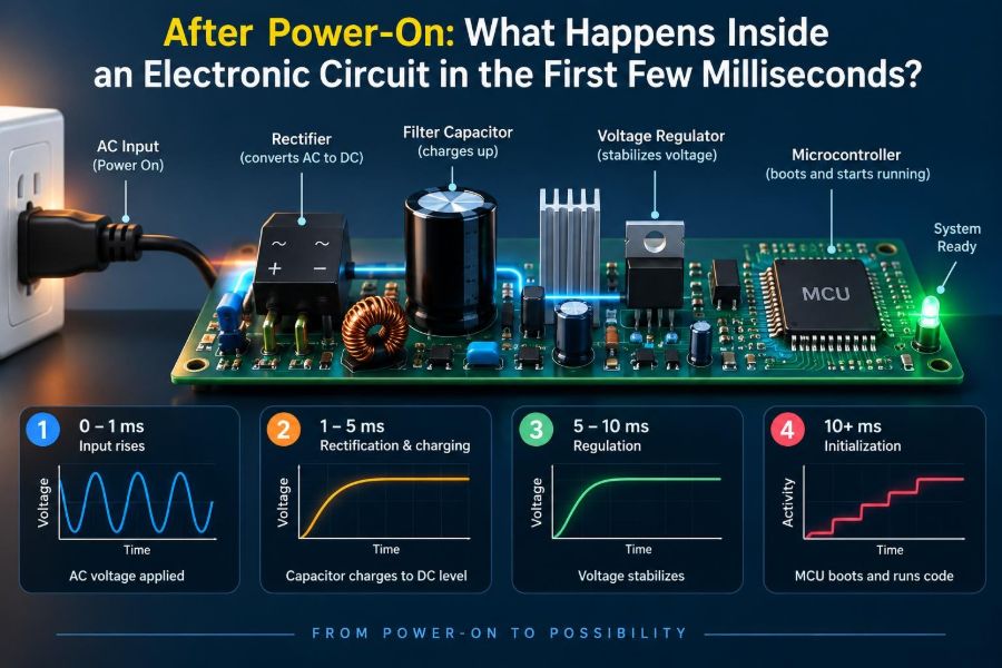
Inside, however, the first few milliseconds are rarely calm. Voltages rise along different paths, capacitors draw short bursts of current, clocks settle, reset circuits make decisions, and digital devices must avoid acting before their supplies are trustworthy.
That brief interval is called power-up transient behavior. It is easy to overlook because it happens before normal operation, yet it explains many familiar faults: a board that only starts after a second press, a microcontroller that occasionally boots into the wrong mode, or a regulator that collapses when a motor is connected.
Understanding startup means treating power as a sequence rather than a simple on/off event. Here is what a circuit is doing while it crosses the boundary between unpowered hardware and a functioning electronic system.
⚡ Power-On Is a Transition, Not an Instant
A supply is often drawn as a clean step from 0 V to its rated voltage. Real sources do not behave that way. Their output climbs over a finite time, sometimes smoothly and sometimes with pauses, overshoot, ringing, or brief dropouts.
The shape of that rise depends on the source, wiring, load, regulator control loop, and stored charge in the circuit. A coin cell connected to a small sensor may rise differently from a 48 V industrial supply feeding several converter stages.
🔋 The Source Meets an Initially Empty Circuit
At the first instant of connection, uncharged capacitors look much like a low-resistance load. This does not mean they are permanently short circuits; it means their voltage cannot change instantaneously.
The power source therefore supplies inrush current, the temporary current needed to charge capacitance and establish voltages throughout the circuit. The amount and duration depend on capacitance, resistance, source impedance, and any deliberate current-limiting circuitry.
🧮 Capacitors Set the First Charging Timeline
For a simple resistor-capacitor path, the capacitor voltage rises exponentially toward the supply voltage. The time constant is τ = RC, where R is resistance in ohms and C is capacitance in farads.
After one time constant, the capacitor has reached about 63% of its final change. In real boards, the effective resistance includes cables, switches, traces, capacitor ESR, regulator output impedance, and sometimes active circuitry, so a single RC calculation is only a useful first approximation.
💥 Why Inrush Current Can Be Surprisingly Large
A large bulk capacitor on a low-impedance source can demand a sharp current pulse at connection. Long before the voltage reaches its nominal level, this pulse may stress a switch contact, trip a current limit, pull down a shared supply, or create electromagnetic interference.
For example, a board with several input capacitors may work from a bench supply but fail from a USB port or battery protection circuit. The alternate source may interpret the startup pulse as a fault and disconnect momentarily.
🧱 Resistance Is Not Always a Problem
Some resistance in the charging path slows inrush and damps oscillation. Designers may add a resistor, NTC thermistor, load switch, hot-swap controller, or controlled MOSFET ramp to manage that trade-off.
The cost is a slower rise, some voltage drop, heat during startup, or added component complexity. The right approach depends on whether the system needs quick availability, low noise, limited connector stress, or compliance with a source’s current capability.
📦 Decoupling Capacitors Begin Working Before Logic Does
Small capacitors placed close to integrated circuits are called decoupling capacitors. During normal operation, they deliver rapid local current when an IC switches. At startup, they must first be charged along with everything else.
Their distributed placement matters. A board does not become one uniform voltage node instantly: trace resistance and inductance mean that different IC pins can experience slightly different voltage histories, especially during fast transitions.
📈 Voltage Rails Do Not Necessarily Rise Together
Modern systems often need several rails: perhaps 12 V input, 5 V peripherals, 3.3 V logic, 1.8 V memory, and a low-voltage processor core. Each rail can have a different regulator, load, capacitance, and turn-on delay.
This is called power sequencing. Some devices tolerate arbitrary rail order; others require one supply to be present before another, or require a specific difference between rails while starting.
🔁 What a Voltage Regulator Is Doing at Startup
A linear regulator or switching converter does not simply pass voltage onward. It uses a feedback loop that compares its output with a reference and adjusts its control element to reach the target.
At startup, the loop must move from an inactive state to stable regulation while charging output capacitors. Many regulators include soft-start functions to control the output ramp and reduce current demand, but their actual behavior should be checked in the datasheet under the intended load conditions.
🌀 Overshoot, Undershoot, and Control-Loop Settling
Because regulators are feedback systems, their output may briefly exceed or fall below the target during a sudden change. A well-compensated converter settles quickly, while a poorly matched output capacitor or unusual load can cause ringing or instability.
Overshoot is not merely a cosmetic waveform issue. A rail rated at 3.3 V may be connected to IC pins with limited absolute maximum ratings, so even a very short excursion can matter.
🌊 Parasitic Inductance Creates Ringing
Every wire, trace, connector, and capacitor has parasitic inductance. When current changes rapidly, that inductance resists the change and can combine with capacitance to form an unintended resonant circuit.
The result may be ringing: a voltage that bounces above and below its expected path. Short connections, sensible capacitor placement, damping resistance, and careful measurement all help control or correctly observe this behavior.
🔌 Cables and Connectors Are Part of the Circuit
A power cable is not an ideal conductor. It adds resistance and inductance, while a connector can add contact resistance that changes with wear, vibration, or contamination.
When a distant load starts, its inrush current can make the voltage at the board temporarily lower than the voltage at the source. This is why a system may behave differently on a short laboratory lead than on the longer cable used in the product.
🧲 Inductive Loads Do Not Start Like Resistors
Motors, relays, solenoids, and transformers include inductance, which resists rapid current change. A motor also has little or no back electromotive force before it turns, so its startup current can be much greater than its running current.
That load may pull a logic supply down just as the controller tries to boot. Separating motor and logic power paths, using adequate bulk capacitance, and applying proper flyback protection are common design measures.
🧠 Digital ICs Have an Undefined Zone
Digital logic requires supply voltage and input signals to stay within defined operating ranges. Below those ranges, a logic gate may not interpret a high or low level reliably, and its internal transistors can be only partly switched on.
This condition is often called brownout operation. It can cause unpredictable states, excess current, corrupted communication, or partial execution in programmable devices. A circuit should not assume that a slowly rising supply produces a clean digital beginning.
🛑 Reset Holds the System Still
A reset circuit keeps a processor, FPGA, or peripheral inactive until power and often the clock are valid. Reset is not just a restart button; it is a controlled boundary between uncertain electrical conditions and intentional operation.
A basic reset resistor-capacitor network may be adequate in a simple circuit, but it can be inaccurate with slow ramps, leakage, temperature variation, or a supply that dips after initially rising. Dedicated supervisor ICs provide a defined threshold and delay.
👁️ Brownout Detection Watches for a Safe Supply
Many microcontrollers contain brownout detection, which monitors the supply and resets or holds the CPU when voltage falls below a selected threshold. It protects against both startup and later battery droop.
Its limitations matter. Threshold options are discrete, accuracy has tolerance, and not every internal peripheral is protected in the same way. External supervisors are still useful where a precise threshold, long delay, or monitoring of multiple rails is needed.
⏱️ Reset Release Needs More Than a Voltage Threshold
Releasing reset exactly when a rail crosses its nominal minimum may still be too early. A crystal oscillator may not be stable, another supply may be late, and external memory may need time to initialize.
Good startup design considers the whole dependency chain: power-good signal, reset timing, clock readiness, configuration straps, and firmware initialization. The relevant question is not only “Is voltage present?” but “Is the system ready to make reliable decisions?”
🕰️ Clocks Need Time to Become Trustworthy
Microcontrollers can use internal RC oscillators that start quickly, but their frequency is less accurate than a crystal under changing voltage and temperature. Crystal and resonator oscillators may require a startup period before their amplitude and frequency stabilize.
Some chips automatically wait for the oscillator; others require firmware or external logic to manage it. Clock failure detection can add resilience, but it cannot replace proper startup conditions.
🧷 Configuration Pins Are Sampled Early
Many ICs read boot-mode, address, enable, or configuration pins during reset release. These pins are often called strap pins because fixed resistors “strap” them high or low.
If an external device drives a strap pin too early, too late, or while its own supply is absent, the IC can select an unintended mode. Pull resistors, isolation resistors, and documented timing requirements prevent these subtle failures.
🚪 Unpowered ICs Can Be Powered Through Their Inputs
Suppose a 3.3 V signal enters an IC whose 3.3 V rail is still at 0 V. Internal protection structures may conduct current from the signal pin into the unpowered supply rail. This is known as back-powering.
Consequences range from a harmless small leakage current to a partially energized chip, incorrect startup, or damage beyond the device’s injection-current limit. Level translators with power-off protection, series resistance, correct sequencing, and output-enable control can address it.
🗣️ Buses Must Wait for Their Partners
Shared interfaces such as I²C, SPI, UART, CAN, and Ethernet connect devices that may not power up together. An unpowered peripheral can clamp a line, while a controller may transmit before the receiver is ready.
For I²C in particular, pull-up resistors can expose sequencing problems because every connected device shares the same lines. Bus switches, reset control, enable pins, and firmware delays are possible tools, chosen according to the interface and fault requirements.
💾 Memory Is Not Automatically Ready at Power-On
External flash, SDRAM, EEPROM, and storage devices can have their own power-up timing, reset requirements, and command restrictions. Memory contents may survive an interrupted write, but the data structure using that memory may not be consistent.
Firmware should distinguish electrical startup from application readiness. A robust system validates configuration data, handles incomplete transactions where relevant, and does not assume that every previous shutdown was clean.
🧩 Programmable Logic Has Its Own Startup Path
FPGAs and some complex programmable devices often load configuration data after power is applied. During this interval, their I/O pins may be high-impedance, weakly pulled, or governed by device-specific startup rules.
Board designers must account for what connected devices see before configuration completes. An apparently harmless floating control line can enable a power stage, select a mode, or create a contention condition.
🔄 Firmware Takes Over After Hardware Is Stable
Once reset is released, processor startup code initializes stack memory, clocks, peripheral registers, and interrupt behavior before the application performs its visible task. This software phase can still expose power-up design weaknesses.
For example, firmware that enables a high-current radio immediately after boot may trigger a supply dip that the hardware startup sequence had avoided. Staged enabling, voltage checks, and conservative default output states make the handoff smoother.
📉 A Brief Dip Can Be More Dangerous Than a Slow Rise
A rail may rise correctly, release reset, and then sag when a display backlight, motor, or communication module starts. If the dip crosses a brownout threshold only briefly, the result can be repeated resets or a device that hangs in an unusual state.
This is why startup testing must include realistic loads and firmware activity. Observing only the unloaded regulator output can create false confidence.
🔍 Measuring the First Milliseconds Correctly
An oscilloscope is the most useful tool for examining startup, but the probe connection can change what you see. A long ground clip adds inductance and can exaggerate high-frequency ringing; a short ground spring or low-inductance probing method is better for fast edges.
Trigger on the input voltage, enable signal, or reset release. Capture several channels when possible: input rail, regulated rail, reset, clock, and a load-enable signal often reveal the true sequence.
📊 What to Put on a Startup Timing Diagram
A timing diagram turns a vague “it starts sometimes” report into observable relationships. Mark threshold crossings and note which signals must precede others.
| Signal | Useful observation | Typical question |
|---|---|---|
| Input supply | Ramp, droop, cable loss | Does the source sag during inrush? |
| Regulated rail | Rise time, overshoot, ripple | Does it reach regulation before reset ends? |
| Reset or power-good | Threshold and delay | Is it released after all required rails settle? |
| Load enable | Sequence of current demands | What event causes a post-boot dip? |
🧪 Test More Than the Ideal Power Supply
A bench supply with thick leads and adjustable current limit is valuable, but it may conceal product-level problems. Test the intended adapter, battery range, cable length, and realistic peripheral load where safe and practical.
Also test rapid off-on cycles and partial discharge. Capacitors can retain charge while one rail falls faster than another, producing a different sequence from a completely cold start.
🌡️ Temperature, Tolerance, and Aging Change Startup
Capacitance, equivalent series resistance, oscillator behavior, battery internal resistance, and regulator thresholds all vary with temperature and manufacturing tolerance. Electrolytic capacitors can change noticeably with age and temperature, especially in demanding environments.
Design margin is therefore more valuable than a waveform that barely passes at room temperature on one prototype. The goal is a startup sequence that remains valid across credible conditions, not only a favorable laboratory moment.
⚠️ Common Power-Up Design Mistakes
- Assuming a regulator’s nominal output voltage says enough about its startup behavior.
- Connecting signals between domains without considering which side powers first.
- Using reset only as a manual button rather than as a supply-valid control.
- Ignoring the startup current of motors, radios, displays, and storage devices.
- Measuring a fast transient with a probe setup that creates misleading ringing.
- Testing only cold starts, not brownouts and quick power cycles.
None of these mistakes is unusual. They arise because a schematic shows connectivity clearly but does not automatically show time-dependent behavior.
🛠️ A Practical Startup Design Checklist
Before committing a design, write down the required rails, their permitted order, expected loads, reset dependencies, and external signals that may be present when power is absent. This converts assumptions into reviewable engineering requirements.
- Estimate inrush and verify source current capability.
- Read regulator soft-start, stability, and enable specifications.
- Use defined pull states for control and configuration pins.
- Protect against back-powering across voltage domains.
- Sequence high-current loads after core logic is stable.
- Capture real startup waveforms under representative conditions.
🏁 The Core Principle: Establish Order Before Operation
The first milliseconds after power-on are a negotiation among energy storage, source impedance, regulators, logic thresholds, clocks, and software. A successful circuit does not merely reach the correct final voltages; it reaches them in an order and at a rate its components can tolerate.
That perspective helps explain why startup faults can seem random. The final state may look normal, while a short-lived undervoltage, premature signal, or current pulse has already pushed a device into the wrong state.
When power-up behavior is designed deliberately, reset and sequencing create a clean starting line. Hardware begins from valid electrical conditions, and firmware can begin from valid assumptions.
Reliable electronics treat power-on as a controlled process, not as the moment after the circuit has already started. A few captured milliseconds can reveal the reason a system succeeds, fails, or only works by luck. 🔌📈🛠️