
A desk lamp dims without becoming yellow. A cordless drill eases into a screw instead of immediately running at full speed. A phone charger regulates energy delivered to a battery while staying compact enough to fit in a pocket.
These devices appear to “turn power up and down,” but many do not reduce voltage in the simple, continuous way people imagine. Instead, they switch power on and off very quickly.
That method is called pulse-width modulation, or PWM. It is one of the most practical ideas in electronics because a switch wastes far less power when it is fully on or fully off than when it is held halfway between those states.
Understanding PWM helps explain LED dimmers, motor controllers, switched-mode power supplies, audio amplifiers, solar chargers, and much of modern embedded electronics. The basic waveform is simple; choosing and applying it well is where engineering begins.
⚡ PWM in one sentence
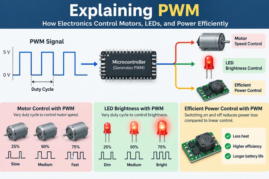
PWM controls the average power sent to a load by repeatedly switching a signal between two voltage levels and changing how long it stays on during each cycle.
Imagine a 12 V supply connected to a motor for half of every cycle and disconnected for the other half. At a sufficiently high switching rate, the motor responds roughly as though it receives less than full drive, while the controller itself spends most of its time in efficient switching states.
PWM is not inherently a lower-voltage output. At any instant, the signal may still be near 0 V or 12 V. Its useful effect comes from time averaging and from the electrical or mechanical behavior of the load.
📏 The pulse, period, and frequency
A PWM waveform is a train of rectangular pulses. One complete on-and-off pattern is a period, usually written as T. Frequency, written as f, is the number of periods per second: f = 1/T.
For example, a 1 kHz PWM signal repeats 1,000 times each second, so its period is 1 millisecond. If each pulse stays high for 0.25 milliseconds, the rest of that period is low.
Frequency matters because loads cannot all respond equally well to rapid switching. An LED may visibly flicker at an unsuitable rate, a motor may make audible noise, and a power converter may suffer higher switching losses as frequency rises.
⏱️ Duty cycle is the main control variable
The duty cycle is the percentage of one period for which the PWM signal is on. It is commonly expressed as D = ton/T, or as a percentage.
- At 0% duty cycle, the output is always off.
- At 25%, it is on for one quarter of each cycle.
- At 50%, on-time and off-time are equal.
- At 100%, it is continuously on.
With a 12 V waveform driving a resistive load, an ideal 25% duty cycle has a time-averaged voltage of about 3 V. That statement is useful, but it does not mean the load sees a smooth 3 V at every moment.
📊 Average voltage and average power are not interchangeable
For an ideal PWM signal that switches between 0 V and VIN, average voltage is approximately D × VIN. This is often a helpful starting point for LEDs, filtered signals, and conceptual explanations.
Power calculations require more care. A resistor’s heating depends on the square of instantaneous voltage, so its equivalent heating is tied to RMS voltage, not merely average voltage. For an ideal PWM waveform applied to a resistor, VRMS is VIN × √D.
A motor adds inductance, back electromotive force, friction, and inertia. A battery is electrochemical rather than purely resistive. PWM behavior must therefore be considered with the actual load model, not just one convenient formula.
🔘 Why switching is more efficient than throttling
A transistor used as a linear control element can sit in a partially conducting state. It then has substantial voltage across it while substantial current flows through it, producing heat equal to voltage times current.
A PWM transistor is designed to spend most of its time either fully off, with nearly zero current, or fully on, with a small voltage drop. In either state, its dissipation can be much lower than in the middle region.
There is no free energy: losses still occur during transitions, in wiring resistance, and in magnetic components. Yet switching control is often dramatically more practical than dissipating unwanted energy as heat in a transistor or resistor.
🔄 What happens during each switching edge
Real switches do not change state instantly. During turn-on and turn-off, voltage and current overlap for a short interval, and that overlap causes switching loss.
Fast edges reduce the duration of the overlap but can create ringing, electromagnetic interference, and voltage overshoot caused by stray inductance. Slower edges can be quieter electrically but increase heat in the switching device.
Good PWM design balances these competing effects through suitable gate-drive strength, layout, snubbers where needed, and a frequency appropriate to the application.
💡 Dimming LEDs with PWM
An LED’s brightness is closely related to its average current over time. PWM can control perceived brightness by driving the LED at a chosen current during the on portion, then turning it fully off during the remaining portion.
This differs from analog dimming, which lowers LED current continuously. PWM can preserve color behavior and current-regulator operation in many designs, though the outcome depends on the LED driver and the LED chemistry.
For a simple low-power LED circuit, a resistor still limits current during every on pulse. PWM is not a substitute for current limiting. Connecting an LED directly to a voltage source and merely pulsing it can exceed its safe current rating.
👁️ Flicker, cameras, and LED frequency
Humans do not perceive flicker in exactly the same way under all conditions. Peripheral vision, motion, brightness level, and individual sensitivity can make a frequency that seems acceptable in one setting distracting in another.
Cameras introduce a separate problem. A rolling shutter samples different parts of an image at slightly different times, so PWM lighting can produce dark bands even when it appears steady to the eye.
There is no single PWM frequency that solves every lighting case. Designers choose a frequency with the dimming range, driver losses, camera requirements, wiring, and intended environment in mind.
🛞 Motor speed control starts with torque
For a brushed DC motor, PWM applies full supply voltage in short intervals. The winding inductance smooths current to some degree, and the rotating mass smooths mechanical speed, allowing speed and torque to be controlled efficiently.
Motor torque is primarily related to current, not simply commanded duty cycle. At low speed or under a sudden load, current can rise sharply because back electromotive force is lower. A controller that only changes duty cycle may not adequately protect the motor or transistor.
Higher-level motor drives often measure current and use feedback, so PWM becomes the actuator inside a broader speed or torque control loop.
🧲 Inductance makes motor PWM different
A motor winding resists rapid changes in current. When a switch turns off, the winding current still needs a path. Without one, voltage can rise high enough to damage the switching transistor.
A flyback diode across a brushed DC motor gives current a safe recirculation route when a low-side switch turns off. In more advanced bridge drivers, transistors and diodes provide controlled freewheeling paths.
The current waveform depends on supply voltage, winding resistance, inductance, motor speed, load torque, duty cycle, and switching frequency. This is why a motor cannot be treated exactly like a lamp or resistor.
🔊 The source of PWM motor noise
Motors can physically vibrate at frequencies related to switching, current ripple, or control-loop behavior. If those frequencies lie in the audible range, a motor, its mount, or nearby components may whine.
Raising frequency can move a tone beyond much of human hearing, but it also raises transistor switching losses and may worsen electromagnetic emissions. Lowering frequency reduces switching loss but can make torque ripple or noise more obvious.
Mechanical construction matters too. A well-mounted motor with appropriate current control may sound very different from the same motor on a resonant plastic enclosure.
🔋 PWM in switching power converters
Buck, boost, and buck-boost converters use PWM to regulate energy transferred through inductors and capacitors. Rather than dropping excess voltage as heat, they store energy briefly in a magnetic field and release it in a controlled way.
In a buck converter, changing duty cycle influences output voltage. In an idealized continuous-conduction buck converter, output voltage is approximately duty cycle times input voltage. Real converters also require feedback compensation, current limits, suitable inductors, capacitors, and careful layout.
This is a deeper use of PWM than merely chopping power to a load: the inductor and capacitor actively convert the pulsed energy into a controlled DC output.
🧮 PWM versus a true analog voltage
A PWM pin on a microcontroller does not usually produce a continuously variable voltage. It produces a digital waveform. If an analog voltage is needed, a low-pass filter can average the pulses.
A resistor-capacitor, or RC, filter is the simplest example. The resistor limits charging current into the capacitor, while the capacitor smooths the rapid changes. More filtering reduces ripple but also slows the response to a duty-cycle change.
This trade-off is fundamental: a filter that reacts quickly tends to leave more PWM ripple, while a very smooth output takes longer to settle. Precision applications may use a digital-to-analog converter instead.
🎛️ Resolution: how finely duty cycle can change
PWM resolution describes how many distinct duty-cycle values a controller can command. An 8-bit PWM unit commonly provides 256 count positions, while a 12-bit unit provides 4,096 positions.
More bits can make fine dimming or precise control easier, but useful resolution depends on the timer clock and selected frequency. A controller has a finite number of timer counts available in each period.
At higher PWM frequency, a fixed timer clock leaves fewer counts per cycle, reducing duty-cycle granularity. Engineers must choose a practical compromise rather than assuming the highest frequency and highest resolution are available simultaneously.
🧠 Timers create reliable PWM signals
Microcontrollers commonly generate PWM using hardware timers. A counter repeatedly counts through a set range, and comparator logic changes an output state when the count reaches a programmed threshold.
Hardware PWM is preferable to a software loop that manually toggles a pin because it maintains timing while the processor handles other tasks. It also supports synchronized channels, complementary outputs, dead time, and trigger events on many devices.
Software-generated PWM can still be appropriate for slow, noncritical tasks, but interrupt latency and variable code execution can introduce jitter that is unacceptable in precision control or power electronics.
🌊 Edge-aligned and center-aligned PWM
In edge-aligned PWM, pulses begin at one end of the timer period and their trailing edge moves as duty cycle changes. It is straightforward and common in general-purpose microcontroller outputs.
Center-aligned PWM counts up and down, placing pulses around the middle of a cycle. It can reduce certain harmonic effects and is valuable in motor drives and power converters, especially when sampling current at well-defined points.
The best choice depends on the system. The waveform mode affects measurement timing, switching symmetry, electromagnetic behavior, and how easily multiple channels can be coordinated.
🔀 H-bridges reverse motor direction
A single low-side transistor can switch a motor on and off in one direction. To reverse direction electronically, a common solution is an H-bridge: four switches arranged so current can flow through the motor either way.
PWM can then regulate speed while the chosen switch pair determines direction. Some bridge states allow coasting, while others actively brake the motor by providing a low-resistance current path.
Never turn on both switches in the same bridge leg at once. This creates shoot-through, a direct path from supply to ground that can rapidly damage components or overload a power source.
⏳ Dead time prevents shoot-through
Real transistors do not turn off at the exact instant another transistor turns on. In half-bridges and H-bridges, controllers insert a short intentional gap called dead time between complementary switching commands.
Too little dead time risks cross-conduction. Too much dead time causes current to flow through body diodes or other less efficient paths, increasing distortion and losses.
Dead-time selection depends on transistor characteristics, gate-driver behavior, operating current, temperature, and circuit parasitics. It should be verified with measurements, not chosen only from a generic example.
📡 Electromagnetic interference needs attention
Fast PWM edges contain high-frequency energy. Long wires can behave like antennas, and loop inductance can turn a small layout mistake into ringing, emissions, or unreliable sensor readings.
Useful practices include keeping high-current switching loops short, placing decoupling capacitors close to switching devices, separating sensitive analog routes from noisy power paths, and using suitable grounding strategies.
Ferrites, snubbers, shielding, and controlled edge rates can help in particular cases. They are not replacements for sound physical layout, which is often the first and most effective line of defense.
🌡️ Thermal design still matters
Efficient PWM control does not mean components stay cool automatically. MOSFET conduction loss rises with on-resistance and current. Switching loss rises with voltage, current, transition time, and frequency.
Diodes, inductors, connectors, wires, current-sense resistors, and capacitors also dissipate energy. A motor controller may fail at a connector or diode even when its main transistor appears adequately rated.
Estimate losses, inspect component temperature under realistic load, and allow margin for a warm enclosure and supply variation. Thermal behavior is a system property, not a single-device specification.
🧯 Protecting switches and loads
Practical PWM circuits need protection against conditions that ideal diagrams omit. A motor can stall, a supply can be connected backward, a wire can short, and a battery can deliver far more current than a small board can tolerate.
- Use current limiting or fast overcurrent shutdown where fault energy is significant.
- Choose voltage ratings with margin for transients, not only nominal supply voltage.
- Use flyback paths, transient suppression, or snubbers appropriate to inductive loads.
- Consider fuses, reverse-polarity protection, thermal monitoring, and safe startup behavior.
Protection choices must fit the energy source and fault scenario. A USB-powered prototype and a large battery-powered actuator require very different levels of fault containment.
🧪 Measuring PWM correctly
A multimeter may show a useful average or RMS-related reading, but it rarely reveals waveform shape, overshoot, ringing, or brief current spikes. An oscilloscope is usually the right tool for examining a PWM node.
Probe grounding is especially important. A long ground lead adds inductance and can make ringing appear worse or different from the actual circuit behavior. Use a short ground spring when measuring fast switching nodes if the probe supports it.
For current, use an appropriate current probe, shunt resistor with careful differential measurement, or a purpose-built monitor. Avoid connecting an earth-referenced scope ground clip where it could short a live power node.
🧰 A simple LED PWM example
Suppose a 5 V microcontroller controls one indicator LED using a logic-level MOSFET. The LED and its series resistor connect to 5 V, and the MOSFET switches the return path to ground.
At 100% duty cycle, the LED receives its designed current continuously. At 10%, it receives that current for only one tenth of the time. A PWM frequency high enough to avoid obvious flicker produces a dimmer visual result.
The resistor is selected from the supply voltage, LED forward voltage, and desired pulse current, while respecting both the LED’s ratings and the transistor’s capability. The microcontroller pin drives a gate; it does not carry the LED current itself.
🚗 A brushed-motor PWM example
Consider a small 12 V fan driven by a low-side MOSFET. The microcontroller sends PWM to a gate driver or appropriately designed gate network, while a flyback diode is placed across the motor with the correct polarity.
At a moderate duty cycle, the fan may run slowly after it starts. But startup can require more torque than steady rotation, so a low duty cycle that maintains rotation may not start the fan from rest.
A practical controller may apply a brief higher-duty startup command, monitor current, then reduce to the requested operating value. This is an application-specific strategy, not a universal setting.
🔌 PWM and battery-powered equipment
PWM is especially valuable in battery-powered devices because wasting energy as heat reduces runtime and can create uncomfortable enclosure temperatures. Motor drivers and regulators therefore often use switching techniques.
However, pulsed input current can stress a battery, wiring, and input capacitors. A battery’s internal resistance and the wiring inductance affect voltage sag and transient behavior when current changes quickly.
Place bulk and ceramic decoupling capacitors near the driver, size conductors for expected current, and account for battery voltage over its usable discharge range. A controller that works from a bench supply may behave differently on a small battery pack.
🎵 Class-D audio uses a related idea
Class-D audio amplifiers use high-frequency switching and filtering to reproduce an audio waveform efficiently. Although the modulation and feedback details can be sophisticated, the central principle resembles PWM: control energy transfer with rapidly switching devices.
The speaker and output filter respond mainly to the desired audio-frequency content rather than the raw switching waveform. Design requirements are demanding because distortion, electromagnetic interference, stability, and load variation all matter.
This example shows that PWM is not confined to dimmers and motors. It is a broad switching-control technique used wherever efficient power processing is needed.
⚠️ Common PWM mistakes
Many failures begin with treating PWM as a software-only feature. The firmware can command a clean duty cycle while the hardware overheats, the motor emits noise, or transients exceed a component’s rating.
- Driving a motor directly from a microcontroller pin instead of using a suitable power stage.
- Omitting a flyback path for an inductive load.
- Choosing a MOSFET that is not fully enhanced at the available gate voltage.
- Assuming duty cycle alone limits motor current during stall.
- Using high frequency without checking switching loss and electromagnetic interference.
- Ignoring supply decoupling and the resistance of connectors or breadboard wiring.
Each issue has a practical remedy, but the remedy begins with identifying the current path and energy stored in the system during every switching state.
🧭 Choosing a suitable PWM frequency
There is no universal “best” PWM frequency. Begin with the load and the requirement: visible flicker, acoustic noise, control bandwidth, current ripple, switching losses, and electromagnetic compatibility all point in different directions.
LED dimming may prioritize visual behavior and camera performance. A motor drive may balance acoustic output against heat. A converter may select frequency based on inductor size, efficiency targets, control-loop design, and emission limits.
Start with a defensible range from the component data sheets and application context, then measure temperatures, waveforms, noise, and load response. Frequency is an engineering choice to validate, not a magic number to copy.
🧩 PWM works best with feedback
Open-loop PWM sets duty cycle and hopes the load behaves as expected. That can be sufficient for a decorative LED or a lightly loaded fan, but supply voltage, temperature, friction, and load can change the result.
Closed-loop control measures an outcome such as current, speed, voltage, position, or temperature and adjusts PWM to reduce error. A thermostat-controlled heater, a regulated buck converter, and a speed-controlled motor all use this general approach.
Feedback adds sensing, software or analog control, and stability concerns. When designed carefully, it makes PWM a means of regulation rather than merely a fixed power setting.
✅ The core principle to remember
PWM controls power by controlling time. A switch applies energy in carefully timed packets, and the load, filters, or feedback loop converts those packets into useful light, motion, heat, sound, or regulated voltage.
Its strength comes from operating power devices mostly in low-loss on and off states. Its limitations come from the real world: switching transitions, inductive transients, finite timer resolution, noise, thermal stress, and changing loads.
The most reliable PWM designs consider the complete path from supply to switch to load and back again. They also measure the actual waveform and current instead of relying only on an average-voltage calculation.
PWM is efficient not because it makes energy disappear, but because it directs energy through a system at the right times and with the right supporting circuitry. Once that idea is clear, LED dimmers, motor drivers, and switching power supplies become variations of the same powerful engineering pattern. ⚡🔧💡