
Modern electronic systems constantly need to keep signals synchronized. A smartphone must recover timing information from incoming data. A radio receiver must tune accurately to a station. A computer processor must generate stable clock signals. High-speed communication systems must make sure that transmitters and receivers agree on when each bit begins and ends.
One of the most important circuits used to achieve this synchronization is the phase-locked loop, commonly abbreviated as PLL. ⚡
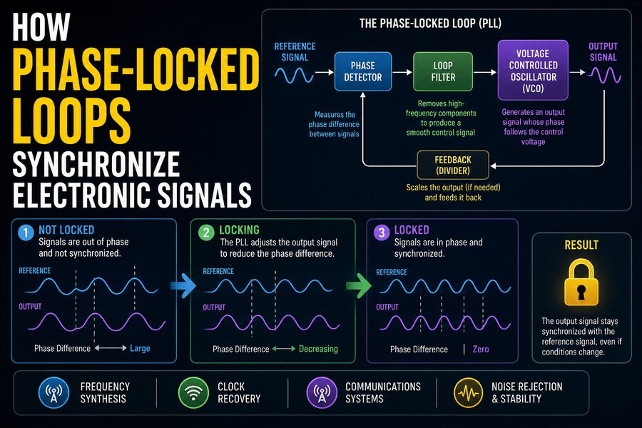
A phase-locked loop is a feedback system that continuously compares two periodic signals and adjusts one of them until their timing relationship becomes stable. In simple terms, a PLL makes an adjustable oscillator follow the frequency and phase of a reference signal.
PLLs appear in radios, televisions, computers, smartphones, satellite systems, networking equipment, GPS receivers, test instruments, motor controls, and countless other electronic devices.
Although the internal mathematics can become sophisticated, the basic idea is surprisingly intuitive.
🕒 What Does “Phase” Mean?
Before understanding a phase-locked loop, it helps to understand phase.
Imagine two sine waves oscillating at exactly the same frequency.
If their peaks and valleys occur at exactly the same moments, the signals are said to be in phase.
If one signal reaches its peak slightly later than the other, there is a phase difference between them.
Phase is commonly measured in degrees.
One complete cycle corresponds to:
360°
If one waveform is shifted by one-quarter of a cycle, the phase difference is:
90°
A half-cycle shift corresponds to:
180°
Phase therefore describes where a periodic signal is within its repeating cycle relative to another signal. 🌊
Synchronization requires controlling this timing relationship.
📡 Why Synchronization Matters
Digital and communication systems rely heavily on timing.
Imagine a receiver trying to interpret a stream of bits:
101101001...
The receiver must know exactly when to sample each bit.
If its internal clock runs too quickly, it may sample some bits twice.
If it runs too slowly, it may miss bits.
Even a tiny frequency mismatch can accumulate over time.
Suppose the transmitting clock runs at 100 MHz while the receiving clock is slightly different.
Initially, the difference may seem insignificant. But after thousands or millions of cycles, their timing can drift enough to cause errors.
A PLL continually corrects this mismatch. 🎯
⚙️ The Three Main Parts of a Basic PLL
A basic phase-locked loop contains three essential functional blocks:
- Phase detector
- Loop filter
- Voltage-controlled oscillator
Modern digital PLLs may use somewhat different implementations, but the fundamental principle remains similar.
The system creates a closed feedback loop.
The oscillator produces an output signal.
That output is compared with a reference.
Any timing error produces a correction signal.
The correction changes the oscillator.
Then the comparison happens again.
This process repeats continuously. 🔄
🔍 The Phase Detector
The phase detector is the component that compares the reference signal with the feedback signal from the oscillator.
Its job is essentially to answer:
“Is the oscillator too early or too late?”
If the feedback signal lags behind the reference, the phase detector generates an error indicating that the oscillator needs to speed up.
If the feedback signal leads the reference, the error tells the oscillator to slow down.
When the signals reach the desired timing relationship, the average phase error becomes very small or reaches the appropriate equilibrium value.
Different types of phase detectors exist.
Some operate with analog waveforms.
Others work with digital pulse signals.
A common digital form is the phase-frequency detector, which can respond to both phase differences and frequency differences. 🧭
🎛️ The Loop Filter
The raw output of a phase detector often contains pulses, rapid variations, or high-frequency components.
Sending this signal directly to the oscillator could make the system unstable or excessively noisy.
The loop filter smooths and shapes the correction signal.
In many PLLs, the filter behaves somewhat like a low-pass filter.
It removes unwanted high-frequency changes while preserving the slower correction information needed to control the oscillator.
The loop filter plays a major role in determining how the PLL behaves.
It affects properties such as:
- Locking speed
- Stability
- Noise rejection
- Response to sudden frequency changes
- Jitter performance
Designing the loop filter is therefore one of the most important parts of PLL engineering. 🛠️
🎵 The Voltage-Controlled Oscillator
The voltage-controlled oscillator, or VCO, generates the PLL’s adjustable output frequency.
Its oscillation frequency changes in response to a control voltage.
For example:
Higher control voltage → higher frequency
Lower control voltage → lower frequency
The exact relationship depends on the oscillator design.
Suppose the reference signal is running slightly faster than the VCO.
The phase detector detects that the VCO is falling behind.
The loop filter produces a correction voltage.
The VCO frequency increases.
As the VCO approaches the correct frequency, the phase difference stops increasing.
Eventually, the loop reaches a stable state. ⚡
At that point, the PLL is said to be locked.
🔐 What Does It Mean for a PLL to Be Locked?
A PLL is considered locked when its output frequency and phase relationship have stabilized relative to the reference.
This does not necessarily mean the two waveforms have absolutely zero phase difference.
A small constant phase offset may exist depending on the PLL architecture.
The important point is that the phase difference is no longer drifting continuously.
If the reference signal changes slightly, the PLL responds by adjusting the oscillator and following the new timing.
This tracking ability is what makes PLLs so useful.
Once locked, the oscillator behaves as though it is connected to the reference through an invisible electronic timing mechanism. 🔗
🚗 A Simple Analogy: Two Cars Matching Speed
Imagine two cars driving along a highway.
The first car is the reference.
The second car represents the PLL oscillator.
A driver in the second car constantly observes the first.
If the distance between them increases, the second driver speeds up.
If the second car gets too close, the driver slows down.
Eventually, both cars travel at the same average speed while maintaining roughly the same separation.
That is similar to PLL behavior.
The phase detector observes the timing difference.
The loop filter determines how strongly to react.
The oscillator changes its speed.
The cycle continues continuously. 🚘
➗ Frequency Dividers Make PLLs Even More Powerful
One of the most useful improvements to a PLL is a frequency divider in the feedback path.
Suppose the oscillator runs at frequency:
Fout
Before feeding the signal back to the phase detector, the circuit divides it by an integer N.
The detector therefore compares:
Fout / N
with the reference frequency:
Fref
When the loop locks:
Fout / N = Fref
Therefore:
Fout = N × Fref
This means a PLL can generate frequencies much higher than its reference.
For example, if:
Fref = 10 MHz
and:
N = 20
then:
Fout = 200 MHz
This technique is called frequency synthesis. 🧮
📻 PLLs in Radio Tuning
One of the classic applications of phase-locked loops is radio tuning.
A radio receiver needs a local oscillator that can generate a precise frequency.
That oscillator helps the receiver select one station while rejecting others.
Older radios often used manually adjusted analog tuning components.
Modern radios commonly use PLL-based frequency synthesizers.
A stable crystal reference might operate at one frequency.
A programmable divider then allows the PLL to generate many different local oscillator frequencies.
Changing the divider value effectively changes the tuning frequency.
This is how electronic tuning can accurately select channels or stations without mechanically adjusting a capacitor. 📡
📱 PLLs Inside Smartphones
Smartphones contain multiple systems that depend on precise clocks.
Wireless communication standards operate at carefully controlled frequencies.
Processors, memory interfaces, radio transceivers, display systems, cameras, and peripheral devices may all require different clock rates.
A crystal oscillator may provide one stable reference frequency.
PLLs then multiply, divide, and distribute this reference to create many other frequencies.
For example, a processor might need a clock in the gigahertz range even though the physical reference crystal operates at only a few tens of megahertz.
A PLL can multiply the lower-frequency reference into the much faster clock required by the processor. 📲⚡
💻 PLLs in Computer Processors
Modern processors depend on extremely precise clock signals.
The clock tells billions of transistors when to coordinate operations.
A motherboard may provide a relatively low-frequency reference clock.
Inside the processor, one or more PLLs multiply that frequency to generate internal CPU clocks.
For example, a reference near 100 MHz might be multiplied to produce a processor frequency of several gigahertz.
PLLs also help generate clocks for:
- Memory controllers
- Graphics processors
- High-speed buses
- Peripheral interfaces
- Communication links
Without reliable clock generation, modern computing systems could not operate at their intended speeds. 🖥️
🔁 Clock Recovery from Incoming Data
PLLs are extremely important in digital communications because data streams often do not arrive with a separate clock signal.
Instead, timing information is embedded in the data itself.
A receiver must reconstruct the clock by observing transitions in the incoming waveform.
This process is called clock and data recovery, or CDR.
The PLL adjusts its internal oscillator until its clock aligns with the timing of the received data.
Once synchronized, the receiver knows when to sample each bit.
Clock recovery is essential in technologies such as:
- Ethernet
- Optical fiber communication
- Serial data interfaces
- Storage systems
- Telecommunications networks
At very high data rates, even tiny timing errors can cause bit errors. 🔌
🎯 Frequency Acquisition vs. Phase Lock
A PLL may begin with its oscillator far from the desired frequency.
Initially, the system must bring the oscillator close enough to the reference for phase synchronization to occur.
This process is sometimes described as acquisition.
The PLL first reduces the frequency difference.
Then it reduces the phase difference.
Eventually, the loop locks.
Some PLL architectures include specialized phase-frequency detectors precisely because they can recognize whether the oscillator is too fast or too slow even when the phase relationship is initially changing rapidly.
This makes acquisition faster and more reliable.
📏 What Is Lock Range?
A PLL cannot necessarily follow every possible frequency.
The lock range describes the range of input frequencies over which the PLL can remain synchronized once it has achieved lock.
Another related concept is the capture range.
The capture range describes the range over which the PLL can successfully acquire lock starting from an unlocked condition.
Depending on the circuit, the capture range may be narrower than the lock range.
Engineers must design PLL parameters so the expected reference frequency remains within appropriate operating limits.
📉 What Is Jitter?
Real electronic signals are never perfectly timed.
Individual clock edges may occur slightly earlier or later than their ideal positions.
These small timing variations are called jitter.
Imagine an ideal clock where an edge should occur every 1 nanosecond.
In reality, edges might occur at:
0.999 ns
1.002 ns
0.998 ns
and so on.
At high data rates, even picoseconds of jitter can matter. ⏱️
PLLs can either reduce certain forms of timing noise or introduce additional noise depending on their design.
Managing jitter is therefore a major concern in high-speed electronics.
🌫️ Phase Noise
Oscillators also exhibit phase noise.
Instead of producing a mathematically perfect frequency, real oscillators experience tiny random fluctuations in phase.
In the frequency domain, this appears as energy spreading around the ideal carrier frequency.
Low phase noise is especially important in communication systems.
Excessive phase noise can reduce signal quality, interfere with neighboring channels, and increase error rates.
PLL designers carefully choose reference sources, oscillators, loop bandwidths, and circuit architectures to minimize these effects. 📶
🎚️ Why Loop Bandwidth Matters
The loop bandwidth describes how quickly the PLL responds to timing changes.
A wider bandwidth allows the PLL to track faster variations in the reference.
However, it may also allow more reference noise to influence the output.
A narrower bandwidth rejects more high-frequency reference noise but responds more slowly.
This creates an important engineering tradeoff.
The designer must decide how much noise should be followed and how much should be filtered.
This balance depends on the application.
A radio synthesizer, high-speed serial receiver, and processor clock generator may all require very different PLL characteristics.
🧩 Analog, Digital, and All-Digital PLLs
Not every PLL is implemented in the same way.
A traditional analog PLL may use an analog phase detector, analog loop filter, and voltage-controlled oscillator.
A digital PLL may replace parts of the loop with digital logic.
An all-digital PLL, or ADPLL, performs much of the control process digitally and may use a digitally controlled oscillator.
Digital techniques can provide advantages such as:
- Easier integration into modern chips
- Programmable control
- Improved calibration
- Reduced sensitivity to certain analog component variations
However, analog PLLs remain valuable in many applications.
The best architecture depends on speed, power, noise, chip technology, and cost.
🔢 Integer-N PLLs
A straightforward frequency synthesizer uses an integer divider.
If the reference is 10 MHz and the divider can be set to integers such as 10, 11, 12, and 13, the possible output frequencies are:
100 MHz
110 MHz
120 MHz
130 MHz
This is known as an integer-N PLL.
Its simplicity can provide excellent performance.
However, the output frequency steps are limited by the reference frequency.
If much finer tuning is needed, another technique may be used.
🧮 Fractional-N PLLs
A fractional-N PLL can generate frequencies corresponding to effectively non-integer division ratios.
For example, the system might behave as though the divider were:
100.25
instead of exactly:
100
or:
This allows very fine frequency resolution without requiring an extremely low reference frequency.
Fractional-N PLLs often use sophisticated digital modulation techniques to alternate among integer divider values in a carefully controlled pattern.
The average division ratio becomes fractional.
These PLLs are widely useful in modern wireless communication systems, but they require careful noise management. 📡
📺 PLLs in Television and Video Systems
Video equipment also depends on precise synchronization.
Displays and video processors must coordinate pixel timing, line timing, frame timing, and high-speed data transfers.
PLLs can recover clocks from incoming video signals or generate internal clocks synchronized to external sources.
This ensures that image data is sampled and displayed at the correct moments.
Similar principles are used in HDMI interfaces, display processors, broadcast equipment, and digital video systems. 📺
🛰️ PLLs in GPS and Satellite Systems
Satellite receivers must process extremely weak radio signals arriving from distant transmitters.
Accurate frequency and phase tracking are essential.
PLLs can help receivers synchronize local oscillators with incoming carriers.
In navigation systems such as GPS, related tracking-loop techniques help maintain alignment with satellite signals despite movement, Doppler shifts, and noise.
The concept is similar to the basic PLL:
Measure timing or phase error.
Adjust a local signal.
Repeat continuously.
Sophisticated receivers may combine several tracking mechanisms to maintain synchronization under challenging conditions. 🛰️
🎛️ PLLs in Motor Control
Phase-locked concepts can also appear in industrial control systems.
Motor drives may need to estimate rotational speed or synchronize electrical signals with mechanical position.
Feedback loops can track periodic signals produced by encoders or sensors.
Synchronizing control waveforms with motor rotation allows power electronics to energize motor windings at the correct times.
Although these systems may use architectures more specialized than a textbook PLL, the underlying principle of tracking phase and frequency remains highly relevant. ⚙️
⚠️ What Happens When a PLL Loses Lock?
A PLL can lose synchronization if conditions change beyond what the loop can track.
Possible causes include:
- Reference signal disappearing
- Excessive noise
- Sudden large frequency changes
- Oscillator limitations
- Power disturbances
- Incorrect configuration
When the loop loses synchronization, the output may drift away from the desired frequency or phase.
Many systems include a lock detector that indicates whether the PLL is currently synchronized.
A processor, radio, or communication system may delay normal operation until its PLL reports stable lock.
🔐 Why Stable Reference Oscillators Matter
A PLL can track and multiply a reference frequency, but it cannot magically create perfect timing from a poor reference.
For this reason, many systems begin with a stable oscillator.
Quartz crystals are commonly used because their mechanical resonance provides excellent frequency stability.
A crystal oscillator may operate at a relatively modest frequency while providing a highly reliable reference.
The PLL then converts that stable reference into other frequencies required by the system.
This combination—stable crystal plus flexible PLL—is found in countless electronic devices. 💎
🔄 Feedback Is the Key Principle
The PLL is fundamentally a negative-feedback control system.
Negative feedback is used throughout engineering.
A thermostat compares actual room temperature with the desired temperature and adjusts heating.
Cruise control compares actual vehicle speed with a target speed and adjusts engine power.
A PLL does something similar with timing.
It compares the oscillator’s phase with the desired phase and adjusts the oscillator to reduce the error.
This continuous comparison-and-correction process allows the system to remain synchronized even when small disturbances occur.
📐 The Mathematics Behind PLLs
At a more advanced level, PLLs can be analyzed using control-system mathematics.
Engineers model components using transfer functions and examine characteristics such as:
- Natural frequency
- Damping factor
- Loop gain
- Stability margins
- Noise transfer
- Settling time
A poorly designed loop may oscillate, respond too slowly, or amplify unwanted noise.
A well-designed loop reaches lock quickly while remaining stable and maintaining low jitter.
This is why PLL design combines electronics, signal processing, feedback theory, and probability. 📊
🧠 Why PLLs Are So Powerful
The remarkable feature of a PLL is that it does not need a perfect oscillator to begin with.
The oscillator only needs to be adjustable and capable of operating near the desired range.
Feedback continuously corrects its timing.
This allows engineers to create:
- Stable clock generators
- Frequency multipliers
- Frequency synthesizers
- Carrier recovery circuits
- Clock recovery systems
- Radio tuners
- Timing distribution networks
One underlying concept can solve many different synchronization problems.
✅ The Bottom Line
A phase-locked loop synchronizes electronic signals by continuously comparing the phase of an adjustable oscillator with a reference signal and correcting any difference.
The phase detector measures whether the oscillator is leading or lagging.
The loop filter smooths the correction.
The oscillator adjusts its frequency.
This feedback cycle repeats until the signals maintain a stable timing relationship.
By adding frequency dividers, PLLs can also multiply reference frequencies and create precise new clock signals.
That is why PLLs are found inside everything from smartphones and processors to radios, fiber-optic links, televisions, GPS receivers, and industrial electronics. 📱💻📡
Whenever electronic systems must agree on exactly when something should happen, there is a good chance a phase-locked loop—or a closely related synchronization circuit—is involved.
It is essentially an electronic system that listens to another signal, measures its timing, and continuously says:
“A little faster… a little slower… perfect—stay right there.” 🔄🎯