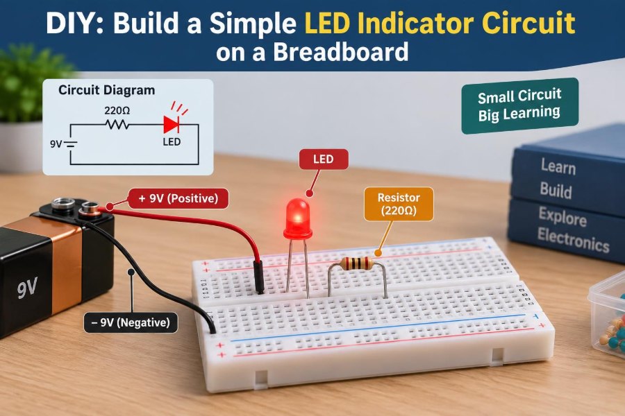

You plug in a new circuit, switch on the power supply, and nothing seems to happen. Is the board powered? Is the polarity correct? Did a wire miss its intended row? A small LED indicator can answer the first question immediately.
An LED circuit is often the first breadboard project because it produces a visible result with only a few components. Yet it also introduces habits that remain essential in larger designs: reading component values, tracing current paths, observing polarity, and checking power before changing parts.
The goal is not simply to make a light turn on. It is to build a circuit whose behavior you can explain: where voltage is applied, how current moves, why the resistor is necessary, and what changes when a connection is wrong.
By the end, you will have a reliable LED indicator circuit and a practical method for diagnosing it when it does not light.
💡 What an LED Indicator Actually Does
An LED, or light-emitting diode, converts some electrical energy into light when current flows through it in the correct direction. In an indicator circuit, that light provides a quick visual signal that a supply rail, logic output, switch, or subsystem is active.
The LED does not measure every property of a circuit. A lit LED usually shows that some current is flowing through its branch. It does not prove that a power supply can deliver enough current for a motor, that a digital signal is clean, or that every part of a design is operating correctly.
🧰 Gather the Essential Parts
This project needs only a few common items. Choose a low-voltage DC source appropriate for a breadboard, such as a regulated 3.3 V or 5 V supply, USB power module, or battery pack.
- One solderless breadboard
- One LED, preferably red for a first build
- One resistor, commonly 220 Ω to 1 kΩ for low-voltage work
- Two or three jumper wires
- A regulated DC power source
- Optional: a digital multimeter
A red LED is convenient because its forward voltage is relatively low, often around 1.8 V to 2.2 V at modest current. That value varies with the device, temperature, and current, so treat it as an approximation rather than a fixed rule.
🛑 Start with a Safe Supply Voltage
Keep the first circuit at low DC voltage. A regulated 3.3 V or 5 V supply is well suited to standard breadboard components and reduces the consequences of a wiring mistake.
Do not connect a breadboard LED exercise directly to mains electricity, wall outlets, or an unknown high-voltage source. Breadboards are intended for low-voltage prototyping; their exposed metal contacts make high-voltage experimentation especially hazardous.
Also check the output voltage of adjustable bench supplies before connection. A supply left at a previous setting can damage an LED or other components much faster than a carefully planned circuit can protect them.
🧱 Understand the Breadboard Connections
A solderless breadboard contains metal clips beneath its holes. On many full-size boards, the central terminal area is organized into groups of five connected holes on each side of a center gap.
Rows on opposite sides of that center gap are normally not connected. The gap exists so integrated circuits can straddle it without their pins being shorted together.
Power rails along the outer edges are often connected lengthwise, but layouts differ. Some rails are split at the middle, and some compact boards omit them entirely. Check the printed markings and, if unsure, use multimeter continuity mode before relying on a rail.
🔍 Read the LED’s Polarity
An LED is polarized. Its anode connects toward the positive side of the circuit, while its cathode connects toward the negative side in this basic arrangement.
- The longer lead is usually the anode.
- The shorter lead is usually the cathode.
- The flat edge on the LED’s plastic rim marks the cathode.
- Inside many clear LEDs, the larger metal structure is the cathode.
Lead length is helpful on a new part, but it becomes unreliable after trimming. Use the flat edge or internal structure when inspecting a reused LED.
🚦 Why Current Direction Matters
A diode is designed to conduct much more readily in one direction than the other. With the anode at a sufficiently higher voltage than the cathode, the LED becomes forward biased and can emit light.
Reverse the LED and it usually blocks current, so it stays dark. Ordinary indicator LEDs are not generally intended to withstand substantial reverse voltage. Low-voltage breadboard supplies often avoid immediate damage, but reversal is still a wiring error worth correcting.
🧯 The Resistor Is Not Optional
An LED is not like a small lamp that can safely be placed straight across a voltage source. Once forward biased, its voltage changes relatively little while current can rise sharply. Without a series resistor or another deliberate current-limiting method, the LED may draw excessive current.
The resistor creates a predictable voltage drop as current increases. That negative feedback is simple: more current produces a larger resistor voltage drop, leaving less voltage available to force even more current through the LED.
Put a current-limiting resistor in series with every ordinary indicator LED. It may go before or after the LED in the same series branch; its position does not alter the branch current.
🧮 Estimate a Suitable Resistor Value
Use Ohm’s law to choose a starting resistor: R = (VS − VF) / I. VS is supply voltage, VF is the LED forward voltage, and I is the desired LED current.
For example, with a 5 V supply, an assumed 2 V red LED forward voltage, and a modest target of 10 mA:
R = (5 V − 2 V) / 0.010 A = 300 ΩA standard 330 Ω resistor is a sensible nearby choice. It gives slightly less current than the calculation, which is usually desirable for a clear, long-lasting indicator. At 3.3 V, a 220 Ω to 470 Ω resistor is often a reasonable starting range for a red LED.
🌈 LED Color Changes the Calculation
Color is not only cosmetic. Different LED materials typically have different forward-voltage ranges. Red and amber LEDs often need less voltage than blue, white, or many green LEDs.
| LED type | Typical forward-voltage tendency | Practical implication |
|---|---|---|
| Red or amber | Lower | Usually easy to run from 3.3 V or 5 V |
| Green | Varies by LED technology | Check the part information when brightness matters |
| Blue or white | Higher | May be dim or fail to light from a low supply with a large resistor |
These are design tendencies, not guaranteed values. Manufacturer data is the best source for a particular LED’s recommended continuous current, forward-voltage curve, and reverse-voltage limit.
📏 Check Resistor Power, Even in Small Projects
The resistor converts electrical energy into heat. Its power can be estimated with P = I²R or P = V²/R, using the voltage across the resistor.
In the 5 V, 330 Ω red LED example, the resistor sees about 3 V at roughly 9 mA. That is only a few hundredths of a watt, comfortably within a typical quarter-watt resistor’s rating.
This check becomes more significant at higher supply voltages or when one resistor is used for a larger current. A resistor that is hot, discolored, or producing a smell is a warning to disconnect power and recheck the circuit.
🗺️ Map the Circuit Before Inserting Parts
The circuit has one simple current path: positive supply, resistor, LED, and negative supply. In schematic form, the order is:
+V ── resistor ── LED anode | LED cathode ── 0 VSketching this path first prevents a common beginner problem: arranging parts by physical appearance rather than electrical connection. A breadboard is only a convenient wiring system; the schematic tells you what must be electrically connected.
🔌 Connect the Power Rails
With power disconnected, connect the positive output of your supply to the breadboard’s positive rail and the supply’s negative output to the negative rail. If your board has split rails, bridge the sections only if you need both sections powered and have confirmed their layout.
Keep wire colors consistent where possible. Red for positive and black or blue for 0 V makes later troubleshooting much faster, especially after several circuit branches share the same board.
🦵 Place the LED Across Separate Nodes
Insert the LED so its two leads do not enter holes that are internally connected together. A convenient method is to place its leads in different rows, perhaps spanning the center gap.
Orient the anode toward the row that will connect to the resistor and positive rail. Place the cathode in a separate row that will ultimately connect to the negative rail.
Do not force the leads. If they are too wide or awkwardly bent, gently shape them with pliers while supporting the lead near the plastic body.
🧷 Add the Series Resistor
Place one resistor lead in the same connected row as the LED anode. Place the resistor’s other lead in a new row. A resistor has no polarity, so either orientation is electrically equivalent.
Then use a jumper wire to connect that free resistor row to the positive rail. Finally, connect the LED cathode row to the negative rail with another jumper.
The completed physical layout may look different from someone else’s layout, but it is correct only if the electrical path remains positive rail → resistor → LED → negative rail.
✅ Perform a Power-Off Inspection
Before applying power, trace the circuit slowly with your finger or a pen tip. Begin at the positive rail, follow the jumper to the resistor, continue to the LED anode, pass through the LED to its cathode, and return through the second jumper to the negative rail.
- Confirm that the LED’s flat side faces the negative return.
- Confirm that resistor and LED share a node at only one intended row.
- Check that no bare jumper accidentally joins positive and negative rails.
- Verify the supply leads are in the correct rails.
This brief inspection is faster than replacing a damaged part after a direct short.
✨ Apply Power and Observe the Result
Turn on the supply. A correctly wired LED should illuminate, although its brightness depends on LED type, resistor value, room lighting, and viewing angle. Some LEDs are highly directional and look dim when viewed from the side.
If the supply has current limiting, set a conservative limit before testing when possible. A current limit does not replace proper wiring, but it can reduce damage when a mistake creates an unintended short.
👀 Judge Brightness Sensibly
Brighter is not automatically better. A high-current LED can be uncomfortable to view, waste battery energy, and operate closer to its thermal limits. Many modern indicator LEDs are visible at currents well below their traditional maximum ratings.
If an LED is too bright at 5 V with 220 Ω, try 470 Ω or 1 kΩ. If it is too dim, first verify wiring and polarity, then consider a smaller resistor while staying within the LED’s specified current limits.
🔄 Reverse the Resistor and LED: What Changes?
Reversing the resistor changes nothing because resistors are nonpolarized. Reversing the LED changes the circuit behavior because the diode direction changes.
This contrast is useful when learning to identify polarized components. Capacitors, diodes, electrolytic capacitors, many integrated circuits, and batteries require orientation checks. Resistors and many ceramic capacitors generally do not.
🧪 Use a Multimeter to Verify the Supply
Set a multimeter to DC voltage and measure from the positive rail to the negative rail. You should see approximately the intended supply voltage, with the positive meter probe on the positive rail.
If the reading is near zero, the supply may be off, disconnected, or shorted. If the meter shows a negative value, the probes are reversed relative to the rail labels; that observation can also reveal that the breadboard wiring is opposite of what you assumed.
Measure voltage rather than current first. Current measurement requires moving the meter into series and using the correct input jack, so an incorrect setup can accidentally short a supply.
📊 Measure the LED and Resistor Voltages
Once the circuit works, measure across the LED and then across the resistor. The two measured voltages should add to approximately the supply voltage, allowing for meter accuracy and connection effects.
For a red LED on a 5 V supply, you might see roughly 2 V across the LED and roughly 3 V across the resistor. Divide the resistor voltage by its resistance to estimate current. For example, 3 V across 330 Ω corresponds to about 9 mA.
This turns a visual project into a first circuit-analysis exercise: voltage is shared around a series loop, while the same current passes through each series component.
🔦 If the LED Does Not Light
Work from the simplest checks to the less obvious ones. Do not randomly move several wires at once; changing one variable at a time makes the fault easier to find.
- Confirm the power source is on and delivering the expected voltage.
- Check that the LED is not reversed.
- Check that each lead is in the intended connected row.
- Verify the rails are not split where you expect continuity.
- Inspect for a loose jumper or a resistor placed one row away.
- Test the LED with a multimeter diode-test function, if available.
Some meters can light a red LED faintly in diode-test mode. A meter that does not light a blue or white LED may simply lack enough test voltage, so that result alone does not prove the LED is faulty.
⚠️ If the LED Gets Hot or Fails
Disconnect power immediately if the LED becomes hot, emits an unusual smell, changes color unexpectedly, or goes dark after initially lighting. Also disconnect if a resistor becomes too hot to touch safely.
Likely causes include a missing resistor, a resistor bypassed by an accidental jumper, excessive supply voltage, or a component value much lower than intended. Replace a suspect LED only after correcting the cause; otherwise the replacement may fail too.
🧩 Common Breadboard Wiring Mistakes
Most first-build faults are mechanical connection errors, not difficult theory problems. The breadboard’s hidden clips make it easy to assume that adjacent-looking holes are connected when they are not.
- Putting both LED leads in the same five-hole strip
- Assuming rails continue across a center break
- Using a resistor in parallel with the LED instead of series with it
- Connecting both supply wires to one rail by mistake
- Reading a resistor’s color bands from the wrong direction
- Using a damaged jumper with an internally broken conductor
Whenever possible, compare the breadboard arrangement to the schematic node by node, not merely by its overall shape.
🎨 Decode the Resistor You Chose
Through-hole resistors often use colored bands to indicate resistance. A 330 Ω resistor is commonly orange, orange, brown, followed by a tolerance band; a 1 kΩ resistor is commonly brown, black, red.
Color codes are useful, but a multimeter provides a better confirmation when one is available. Measure the resistor before insertion if its bands are faded, if you are sorting mixed components, or if the circuit’s brightness does not match expectations.
🔋 Compare Battery and Bench-Supply Behavior
A battery pack can make the circuit portable and demonstrates that LEDs are practical indicators in everyday devices. However, battery voltage changes with chemistry, state of charge, load, and temperature, so brightness can vary over time.
A bench supply makes voltage and current easier to observe and adjust. It is excellent for learning, but its settings must be checked each time. Neither source is universally better; choose the one that matches the experiment and use an appropriate resistor in both cases.
🔘 Add a Switch for Manual Control
A simple pushbutton or toggle switch can be placed in series anywhere in the LED branch. Opening the switch breaks the current path, while closing it restores the path and lights the LED.
For a pushbutton on a breadboard, inspect its pin layout carefully. Many tactile switches have pairs of internally connected pins, and their orientation can be confusing. Place the switch so it spans the center gap when its geometry is designed for that arrangement.
🧠 Drive the LED from a Digital Output
An LED indicator is often connected to a microcontroller pin rather than directly to a power rail. The same resistor rule applies: output pin → resistor → LED → return, or supply → resistor → LED → output pin when the pin is intended to sink current.
Check the microcontroller documentation for per-pin and total current limits. A bright LED may demand more current than a logic pin should provide. For a status indicator, lower current is often adequate and reduces stress on the output.
🔁 Series and Parallel LEDs Are Different Problems
Two LEDs in series share the same current, but their combined forward voltage must remain below the available supply with enough voltage left for current control. This can work well with a sufficiently high supply, but not every 3.3 V or 5 V arrangement has enough headroom.
Two LEDs in parallel should generally each have their own series resistor. LEDs do not naturally divide current equally; small differences in forward voltage can cause one LED to take more current and appear brighter than the other.
🧊 Consider Heat and Component Limits
At indicator-level currents, heat is usually modest, but engineering practice means considering limits before they become visible problems. LED junction temperature affects light output and lifetime, while resistor power rating limits how much heat it can safely dissipate.
Datasheets matter more as a circuit grows beyond a classroom experiment. They specify maximum ratings, recommended operating conditions, pinouts, optical intensity measurement conditions, and sometimes pulse-current limits. A maximum rating is a boundary, not a target operating point.
🧭 Make the Circuit Easier to Debug Later
Neat wiring is a technical advantage, not just an aesthetic one. Use short jumpers, keep signal paths visible, and leave enough space to probe component leads with a meter.
Label the rails in a notebook or take a photo before modifying a working circuit. When you expand the design, you will know which LED indicates supply power and which LED indicates a new signal rather than guessing from wire positions.
🛠️ Turn the Build into a Reusable Test Module
Once reliable, this LED branch can become a quick diagnostic module. Connect it temporarily between a known reference and a point you want to observe, provided the voltage, polarity, and available current are appropriate.
For example, it can show whether a regulated rail is present or whether a simple switch closes. It is not a substitute for an oscilloscope or logic analyzer when signals change quickly; the LED averages rapid transitions and cannot reveal timing details.
📚 Practice Experiments That Teach More
Make one controlled change at a time and record the result. This is how a simple build becomes engineering practice rather than a one-time assembly task.
- Replace 220 Ω with 1 kΩ and compare visible brightness.
- Measure current indirectly from resistor voltage for each value.
- Try red, green, and blue LEDs with the same resistor.
- Insert a switch and identify the open and closed circuit states.
- Deliberately move one jumper to an unconnected row, power off first, and predict why the LED will not light.
Avoid experiments that intentionally remove the current-limiting resistor while power is applied. That teaches little beyond how quickly a component can be overstressed.
🧠 The Core Principle to Carry Forward
A successful LED indicator is a complete electrical system in miniature: a source provides voltage, conductive connections form a closed path, a resistor controls current, and a polarized load converts energy into a useful output.
When a circuit does not work, return to those fundamentals. Is there a source? Is there a complete return path? Is the polarity correct? Is current controlled? Can each connection be verified rather than assumed?
Those questions scale directly to sensors, transistor switches, microcontroller boards, and power electronics. The parts become more complex, but disciplined circuit tracing remains one of the most valuable troubleshooting skills.
Build the LED circuit carefully, measure what you can, and treat every result as evidence about voltage, current, and connection—not just as a light turning on. 🔌💡🧪