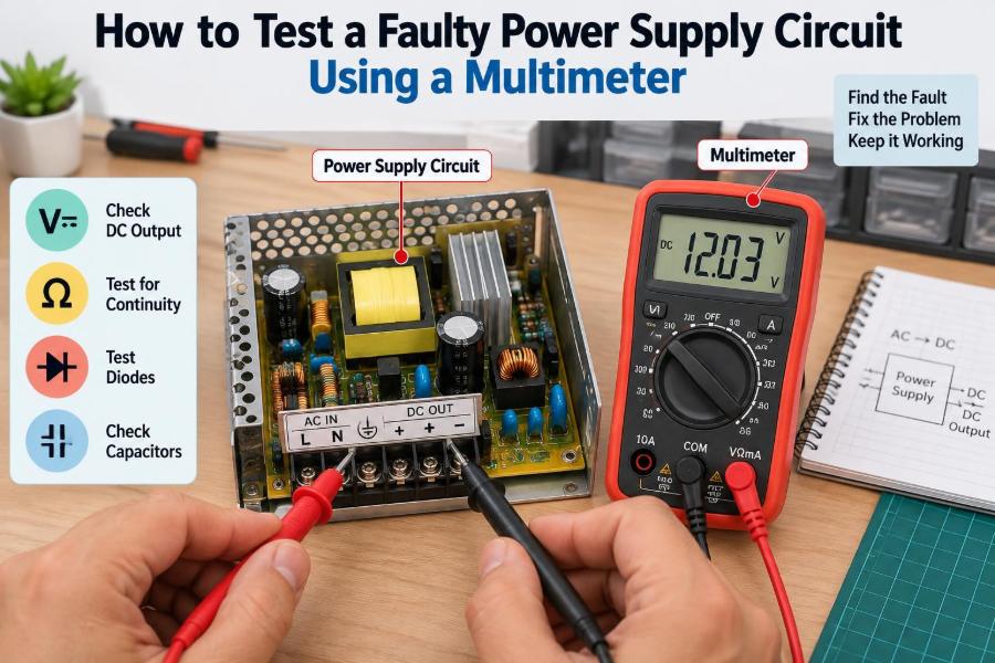

A device that will not switch on often sends people straight to the most visible suspect: the power supply. A dead router, noisy audio amplifier, dim LED driver, or control board that keeps resetting can all point to a power problem—but “the power supply is faulty” is only the beginning of the diagnosis.
A multimeter cannot reveal every failure, especially high-frequency ripple or intermittent faults. It can, however, answer the most useful early questions: Is mains power arriving? Is the fuse intact? Is DC being produced? Is the voltage reaching the load? And where does it disappear?
Good power-supply troubleshooting is less about probing at random and more about following energy through the circuit in a controlled order. That approach protects the technician, protects the equipment, and turns a confusing board into a series of testable stages.
This guide focuses on practical multimeter checks for common linear and switch-mode power supplies. It also explains where a multimeter’s limits begin, because a reading that looks reasonable is not always proof that a supply is healthy.
⚠️ Start With Electrical Safety
Power supplies can contain hazardous voltages, including after they have been unplugged. Mains-powered switch-mode supplies commonly use a large primary-side capacitor that may retain a dangerous charge. Do not assume a dark LED means a circuit is safe to touch.
Work on a dry, uncluttered bench with insulated probes and a meter rated for the voltage category involved. Remove rings, watches, and loose metal jewelry. If you are not trained to work around mains circuitry, restrict testing to the low-voltage output side or seek qualified repair support.
- Disconnect power before changing resistance, continuity, diode, or capacitance ranges.
- Use one hand where practical when measuring live high voltage; keep the other away from conductive surfaces.
- Never bypass a fuse with wire or foil.
- Use insulated probe tips and avoid letting two probe points bridge adjacent conductors.
🧰 Choose a Suitable Multimeter
A basic digital multimeter is enough for many checks, but its condition matters. Verify that the display, probe insulation, input jacks, internal fuse, and rotary switch are sound before trusting any measurement.
For mains work, use a meter with an appropriate CAT safety rating and voltage range. A meter should be selected before the test, not after a surprising reading. Cheap or damaged probes are a weak point even when the meter itself is good.
📏 Understand What Each Meter Mode Tells You
Voltage mode measures electrical potential between two points. Resistance mode applies a small internal test current and estimates opposition to current flow, so it is only for unpowered circuits. Continuity mode is a fast low-resistance check, often indicated by a beep.
Diode mode applies a controlled test voltage and is useful for checking rectifier diodes, LEDs, and transistor junctions. A common mistake is treating continuity as a definitive test for every component; many valid semiconductor paths can beep in one direction.
🔌 Identify the Supply Type Before Testing
A linear power supply typically uses a transformer, bridge rectifier, smoothing capacitor, and regulator. Its test path is easy to visualize: AC enters, lower-voltage AC leaves the transformer, DC appears after the rectifier, then regulated DC reaches the output.
A switch-mode power supply (SMPS) rectifies mains to high-voltage DC, switches it at high frequency, transfers energy through a small transformer, and regulates the output through feedback circuitry. Its primary and secondary sides are normally isolated, so do not casually connect their grounds during measurement.
🗺️ Read the Labels and Trace the Power Path
Before applying probes, inspect connector labels, silkscreen markings, and the supply rating. Note expected outputs such as 5 V, 12 V, 24 V, or dual rails such as +15 V and −15 V. The equipment label often states the required voltage, polarity, and current.
Then trace the likely path from input connector to fuse, switch, transformer or rectifier, filter capacitors, regulators, and output connector. A schematic is ideal, but the board layout and component markings can still establish a logical test sequence.
👀 Perform a Careful Visual Inspection
Look for a blown fuse, loose connector, broken wire, cracked solder joint, scorched resistor, swollen capacitor, leaked electrolyte, or darkened circuit board. These clues do not prove the exact fault, but they focus attention on areas exposed to excess heat or current.
Electrolytic capacitors can fail without visibly bulging, and a component may look burned because another component failed first. Treat visual signs as evidence to investigate, not as automatic permission to replace the most damaged-looking part.
🔋 Check the Input Source First
A faulty battery, power cord, wall adapter, switch, or socket can imitate an internal power-supply failure. Confirm that the source is correct before opening equipment unnecessarily. For a DC adapter, measure at its plug using the stated polarity.
For an AC outlet, use a known-good meter and safe procedure appropriate to your region. If the input source is absent or incorrect, repair upstream rather than chasing components downstream. Power cannot be regulated if it never enters the circuit.
🧪 Verify Your Meter on a Known Voltage
Check the meter on a known-good battery, regulated bench supply, or verified outlet before testing an unknown circuit. This quickly catches a flat meter battery, wrong jack selection, broken probe lead, or an incorrectly selected AC/DC range.
For example, a 1.5 V cell should show roughly its nominal voltage, depending on its condition. If that simple test is implausible, stop and correct the test setup rather than drawing conclusions from the power supply.
🧷 Test the Fuse With Power Removed
Disconnect the supply from power, then test the fuse with continuity or low-ohms mode. A good fuse usually reads very close to zero ohms. An open fuse shows overload, an open circuit, or no continuity indication.
Removing one end of the fuse gives the clearest result, because surrounding circuitry can create misleading paths. A fuse is a protective device, not the root cause: if it has opened, inspect for shorted rectifiers, switching devices, capacitors, wiring faults, or overloads before replacing it.
🔘 Check the Power Switch and Input Wiring
With the circuit unplugged, test a mechanical switch across its terminals. It should show continuity when on and open circuit when off. Flex the cord gently while checking continuity if an intermittent cable break is suspected.
Do not test a live mains switch in resistance mode. If wiring, terminals, or a switch are heat-damaged, replace them with appropriately rated parts. A poor connection can create voltage drop and heating even when it still appears electrically continuous at no load.
🔄 Measure Transformer Secondary AC
On a linear supply, set the meter to AC volts and measure across the transformer secondary winding while powered. The reading should broadly match the transformer’s rated secondary voltage, often somewhat higher with little or no load.
If mains reaches the primary but no secondary AC exists, the transformer, thermal fuse, or primary wiring may be faulty. If secondary AC is present, the fault is likely in the rectifier, filter, regulator, output wiring, or connected load.
🌉 Test a Bridge Rectifier or Individual Diodes
With power removed and capacitors discharged, use diode mode to test rectifier junctions. A healthy silicon diode commonly shows a forward voltage drop in one direction and open circuit in reverse. The exact display depends on the meter and circuit connections.
For an integrated bridge rectifier, identify its AC, positive, and negative terminals from its markings or datasheet. A near-zero reading both ways can indicate a short; open readings both ways may indicate an open junction or an unsuitable in-circuit test.
⚡ Measure the Rectified DC Rail
After a linear transformer and bridge rectifier, measure DC across the main smoothing capacitor: red probe on positive, black probe on negative. The voltage should be higher than the transformer’s AC rating because the capacitor charges near the AC waveform peak.
As a rough guide, unloaded DC after rectification is close to the RMS secondary voltage multiplied by 1.4, minus diode losses. This is an approximation, not a design guarantee. A very low rail points to missing AC, a failed bridge, excessive load, or a shorted capacitor.
💥 Discharge Capacitors Safely
Large capacitors can keep a charge after unplugging. Measure across the capacitor in DC voltage mode to confirm its actual voltage. Never discharge a high-energy capacitor by shorting it directly with a screwdriver; that can damage tracks, tools, and the capacitor itself.
A suitable resistor with an adequate voltage and power rating can discharge a capacitor gradually. The correct method depends on capacitance and voltage, so where there is uncertainty, leave primary-side discharge work to an experienced technician.
📉 Check for DC Rail Collapse Under Load
A power supply may read correctly when disconnected but fail as soon as the load is attached. Measure the output first with no load, then under its normal load if doing so is safe. A major voltage drop suggests overload, weak regulation, excessive resistance, or a supply that cannot deliver current.
For example, a nominal 12 V supply that falls close to zero when connected to a board may be responding to a shorted downstream component. Disconnecting branches one at a time can help isolate which load causes the collapse.
📊 Compare Expected and Measured Readings
| Test point | Expected general result | What an abnormal result may suggest |
|---|---|---|
| Input connector | Specified AC or DC input | Bad outlet, cable, adapter, or switch |
| Transformer secondary | Rated low-voltage AC | Transformer, thermal fuse, or primary fault |
| Main filter capacitor | Stable rectified DC | Bridge fault, missing AC, short, or overload |
| Regulator output | Marked nominal DC rail | Bad regulator, feedback issue, or excess load |
| Load connector | Same rail with limited drop | Connector, cable, trace, or load fault |
Use values printed on the board, service documentation, or component datasheets as the primary reference. A voltage can be slightly above or below nominal depending on load and tolerance; the diagnostic pattern is usually more useful than a tiny deviation.
🎛️ Test Linear Voltage Regulators
Common three-terminal regulators have input, ground, and output pins. With power applied, measure input-to-ground and output-to-ground. The input must be above the intended output by enough margin for the regulator type; this required margin is called dropout voltage.
If input is healthy but output is absent or low, disconnect the load when practical. A restored output suggests a downstream short or overload. If output remains wrong with a known-good input and manageable load, the regulator or its support components are suspect.
🧲 Check for Shorts on Low-Voltage Rails
With power removed, measure resistance between a DC rail and ground. A very low reading can indicate a shorted capacitor, IC, diode, transistor, or solder bridge. However, do not declare a short from one resistance value alone.
Large circuits may naturally show low initial resistance while capacitors charge from the meter, and digital electronics can have low DC resistance. Watch whether the reading rises, compare similar rails, and isolate sections by disconnecting loads or lifting components only when appropriate.
🧯 Understand Why Fuses Blow
A fuse opens when current exceeds its time-current characteristic. A slow-blow fuse may tolerate a brief inrush current, while a fast fuse reacts more quickly. Replacing either with a different type can remove intended protection or cause nuisance blowing.
Common causes include a shorted bridge rectifier, failed MOSFET in an SMPS, shorted main capacitor, damaged cable, or downstream fault. Fit only the specified current, voltage, and speed rating after finding the underlying cause.
🔍 Examine Electrolytic Capacitors Realistically
Filter capacitors smooth rectified voltage and support transient current. When capacitance falls or equivalent series resistance rises, a supply may hum, reset, ripple excessively, or fail under load while still producing a plausible DC voltage on a multimeter.
Some meters offer capacitance measurement, but in-circuit readings can be misleading because parallel components affect the result. An ESR meter or oscilloscope is often more revealing for suspected aging capacitors, particularly in switch-mode supplies.
〰️ Use AC Mode as a Basic Ripple Clue
With the meter on AC volts, measure across a DC output to look for residual AC ripple. This is only a rough screening method because many meters are not accurate for small ripple riding on DC, especially at switching frequencies.
A noticeably higher-than-expected AC reading can support suspicion of failed filtering or overload. It cannot identify waveform shape, transient spikes, or high-frequency noise. For those questions, an oscilloscope is the appropriate instrument.
🧠 Recognize the Special Risks of SMPS Primary Sides
In a mains SMPS, the primary bulk capacitor can hold high-voltage DC after rectification. This area is not low-voltage simply because the circuit uses a small transformer. The primary ground is also not necessarily safe earth or secondary ground.
Do not attach an earth-referenced oscilloscope ground clip to arbitrary primary-side points. For multimeter work, identify measurement references carefully and avoid crossing the isolation barrier with probes. Secondary output checks are usually safer and often sufficient for initial diagnosis.
🔁 Check SMPS Output Rails and Standby Supply
Many modern supplies create a small standby rail before the main outputs start. If an appliance appears completely dead, locate and measure that rail first where documentation or labels identify it. A missing standby voltage can explain why the main controller never receives its start command.
If standby is present but main rails are absent, investigate enable signals, protection shutdown, output shorts, and control circuitry. Measurements on feedback and primary switching stages should be approached only with suitable knowledge and safety controls.
🧷 Test Output Cables, Connectors, and Solder Joints
A healthy supply can seem faulty when its output is lost through a damaged connector, corroded terminal, fractured cable, or cracked solder joint. Measure voltage directly at the supply output and again at the load input while powered.
A meaningful difference between those points reveals voltage drop in the path. With power removed, continuity checks can locate the open connection, but inspect mechanically too: a joint may pass a meter’s tiny test current and fail when real current flows.
🌡️ Use Heat Clues With Caution
Heat can help locate a fault, but it must be interpreted carefully. A regulator, transformer, rectifier, or resistor may normally run warm. Conversely, a shorted device can heat rapidly because abnormal current is flowing.
Do not touch live circuitry to judge temperature. A non-contact infrared thermometer or thermal camera is safer, though shiny surfaces can give misleading infrared readings. Always connect a hot spot to voltage and resistance measurements before deciding it is defective.
🚫 Avoid Common Multimeter Mistakes
- Measuring voltage with the red lead left in the high-current jack, which can create a short through the meter.
- Using resistance or continuity mode on an energized circuit.
- Setting DC mode when checking transformer AC, or AC mode when checking a DC rail.
- Probing two closely spaced pins with uninsulated metal tips.
- Assuming a good no-load voltage proves current capability.
- Replacing components repeatedly without confirming the cause of the failure.
Pause before each measurement and state three things: the expected voltage or behavior, the two points being compared, and the selected meter mode. This simple habit prevents many errors.
🧩 Isolate the Supply From Its Load
Separating the supply from the load is one of the most informative diagnostic steps. If output voltage returns after the load is unplugged, the supply may be functional and the connected circuit may be drawing excessive current.
That result still needs care. Some switch-mode supplies need a minimum load to regulate correctly, while others use remote-sense or enable wiring. Consult available documentation and use a suitable dummy load only if you understand its power rating and connection requirements.
📝 Keep a Measurement Log
Record each test point, meter mode, measured value, load condition, and observed behavior. A short table in a notebook prevents circular troubleshooting and makes patterns clearer—such as input being present, rectified rail being normal, and one regulator output being low.
Photos taken with power removed can help identify connectors and component locations later. Avoid relying on memory when a board has several nearly identical rails or when troubleshooting spans more than one session.
🛠️ Decide When Component Replacement Is Justified
Replace a part when testing, circuit behavior, and inspection support the diagnosis. For example, an open fuse combined with a shorted bridge rectifier supports replacing both only after checking related damage. Replacing every capacitor “just in case” may introduce polarity, voltage-rating, or soldering errors.
Use replacements with suitable voltage, current, temperature, ripple-current, and safety ratings. In mains equipment, safety-rated capacitors, fuses, insulation spacing, and approved component types are part of the circuit’s protection strategy.
🧑🔧 Know When to Stop and Escalate
Stop if you find burned insulation, repeated fuse failures, exposed mains conductors, liquid contamination, damaged batteries, or unexplained high-voltage behavior. These conditions can require isolation equipment, a current-limited source, schematic analysis, or specialized test instruments.
Professional repair is also sensible when the equipment is safety-critical, expensive, proprietary, or connected to medical, industrial, or building systems. Troubleshooting skill includes recognizing when further probing creates more risk than useful information.
✅ Follow the Core Diagnostic Principle
The most reliable method is to follow power from source to load: verify the input, confirm protection devices, check conversion stages, measure the DC rail, test regulation, and compare voltage at the load. At each stage, ask whether the expected energy arrived and whether it remains stable under a reasonable load.
A multimeter is most powerful when it is used to test a hypothesis at one defined point in the power path, not when it is used to hunt randomly for a bad component. That disciplined sequence narrows faults quickly while reducing the chance of unsafe or misleading measurements.
Test methodically, respect stored energy and mains isolation, and let each measurement determine the next one. A clear sequence turns “no power” from a vague symptom into a manageable engineering problem. 🔍⚡🛠️