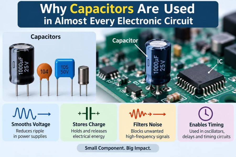

A phone charger that restarts when a cable moves, an audio amplifier that hums, or a microcontroller that behaves strangely near a motor can seem like unrelated faults. Yet many of these problems lead engineers to inspect the same small components: capacitors.
Capacitors often receive less attention than processors, transistors, sensors, or displays. They do not execute code, amplify a signal by themselves, or make a motor turn. Still, without them, many of those more visible parts would operate unreliably—or not at all.
From a simple LED flasher to a computer motherboard and a switched-mode power supply, capacitors manage energy, reduce unwanted noise, shape signals, and establish timing. Their widespread use follows directly from how real circuits behave, rather than from habit.
Understanding why they are present almost everywhere makes circuit diagrams easier to read and helps designers choose values, types, and locations more intelligently.
⚡ A Capacitor Stores Charge
A capacitor consists of two conductive plates separated by an insulating material called a dielectric. When a voltage is applied, charge accumulates on the plates: electrons build up on one plate while an equal shortage of electrons appears on the other.
The dielectric prevents steady DC current from crossing directly between the plates. Energy is instead stored in the electric field between them. This stored energy can later return to the circuit when the voltage conditions change.
Capacitance, measured in farads (F), describes how much charge a component stores for a given voltage. The core relationship is Q = CV, where Q is charge, C is capacitance, and V is voltage.
🪣 A Useful Water Analogy
A capacitor is often compared with a small flexible reservoir in a water system. It can accept water when pressure rises and supply water when pressure falls, helping to smooth short-term changes.
The analogy is useful but incomplete. Electrical charge does not flow through an ideal capacitor in the way water passes through a pipe. Instead, a changing voltage causes current to flow into or out of its terminals while energy moves into or out of the electric field.
That distinction explains a central rule: capacitors respond to changes in voltage. Once a capacitor is fully charged by a constant DC source, ideally no continuing current flows through it.
🔄 Why Changing Voltage Produces Current
The capacitor current relationship is i = C dV/dt. In plain language, current depends on capacitance and on how quickly the voltage across the capacitor changes.
A large capacitor needs more current to change its voltage rapidly. Conversely, a sudden demand for current can cause a smaller voltage change when a larger capacitance is available nearby.
This behavior makes capacitors natural partners for power rails, signal paths, clocks, timers, and switching circuits. Each application uses the same physics in a different way.
🔋 Energy Storage Has Practical Limits
The energy stored in a capacitor is E = ½CV². Doubling voltage therefore increases stored energy by four times for the same capacitance. This is one reason voltage rating matters so much.
Compared with batteries, ordinary capacitors generally store modest energy. Their advantage is not long-duration storage; it is the ability to deliver or accept energy quickly, often over microseconds to milliseconds.
Large capacitors can still retain hazardous charge after equipment is unplugged. Power supplies, camera flash units, motor drives, and high-voltage equipment may require deliberate discharge paths and safe servicing procedures.
🧱 Real Capacitors Are Not Ideal
A schematic symbol suggests a perfect component, but physical capacitors include unwanted resistance, inductance, leakage, and variation. These non-ideal properties determine whether a part works well in a particular location.
Equivalent series resistance (ESR) causes heat when ripple current flows. Equivalent series inductance (ESL) limits performance at high frequency because leads, pads, and internal construction behave like tiny inductors.
Capacitance can also change with temperature, voltage, aging, and applied frequency. Good design means treating a capacitor as a real component with a data sheet, not merely as a number printed on a circuit diagram.
🧭 Capacitor Types Serve Different Jobs
No single dielectric is best for every circuit. The required capacitance, voltage rating, frequency range, stability, physical size, cost, and lifetime all influence selection.
| Type | Common strengths | Typical cautions |
|---|---|---|
| Ceramic | Small, low inductance, effective at high frequency | Some high-capacitance classes vary strongly with DC bias and temperature |
| Aluminum electrolytic | High capacitance and useful bulk energy storage | Polarized, higher ESR than many ceramics, lifetime can be temperature-sensitive |
| Tantalum | High capacitance in a compact package | Requires careful voltage and surge-current consideration |
| Film | Stable, low-loss, suitable for pulse and AC applications | Often physically larger for the same capacitance |
The table is a starting point, not a substitute for checking component ratings under actual operating conditions.
🛡️ Decoupling Keeps Digital ICs Stable
Digital integrated circuits draw current in fast bursts when logic gates switch. The current must travel through traces, package connections, and power-distribution networks, all of which have resistance and inductance.
A decoupling capacitor placed close to an IC supplies part of that fast local current. It reduces the voltage disturbance seen at the chip while the wider power network catches up.
A familiar 100 nF ceramic capacitor near each supply pin is common because it can work well at high frequencies. It is not a universal magic value; package size, IC behavior, board layout, and power-rail impedance all matter.
📍 Placement Is Part of the Component
A capacitor positioned several centimeters from a fast IC may be far less effective than the same part placed beside the supply and ground pins. At high frequencies, the loop formed by the capacitor, traces, vias, and IC behaves inductively.
Keep the current loop short and wide. Connect the capacitor to a low-impedance ground reference, use nearby ground vias when appropriate, and avoid routing that forces high-frequency current around long paths.
This is why a correct bill of materials can still produce an unstable board. Layout determines whether a capacitor can perform its intended job.
🌊 Bulk Capacitors Handle Slower Load Changes
Local ceramics handle very fast transients, but a circuit also needs energy for slower changes: a radio transmitter starting a burst, a motor driver changing load, or a processor entering a demanding operating mode.
Bulk capacitors, often in the microfarad to millifarad range, support these events and reduce low-frequency ripple. Electrolytic, polymer, tantalum, ceramic, or combinations of these technologies may be used.
More capacitance is not automatically better. A large value can increase inrush current, interact with a regulator control loop, consume board area, and cost more. The rail’s transient requirement and regulator guidance should drive the choice.
🔌 Smoothing Rectified Power
After an AC waveform is rectified, its voltage is pulsating rather than perfectly steady. A reservoir capacitor charges near voltage peaks and discharges into the load between them, reducing the depth of the voltage dips.
For a simple supply, ripple grows when load current rises, capacitance falls, or the time between charging peaks increases. This gives the capacitor a clear purpose: it bridges the gaps in available input energy.
In mains-powered equipment, these capacitors may be connected to dangerous voltages. Their voltage rating, ripple-current rating, polarity, discharge provisions, and safety practices must be selected with particular care.
🎛️ Filtering Removes Unwanted Frequencies
A capacitor’s opposition to AC is called capacitive reactance: Xc = 1/(2πfC). As frequency increases, reactance decreases. A capacitor can therefore provide an easier path for high-frequency noise than for low-frequency or DC content.
Paired with resistors, inductors, or active circuits, capacitors create filters. A low-pass filter can smooth sensor noise; a high-pass filter can remove DC offset; a band-pass filter can select a useful frequency range.
Filter performance depends on source impedance, load impedance, tolerances, and layout. Calculated cutoff frequencies are valuable guides, but real measurements remain important in sensitive designs.
📻 Bypass Capacitors Give Noise a Safer Path
In many circuits, “bypass” describes directing unwanted AC energy away from a sensitive node, usually toward ground or another return path. A capacitor near a reference voltage, analog supply, or bias node can reduce disturbances at that location.
The word is sometimes used interchangeably with decoupling, and the functions overlap. A practical distinction is that decoupling emphasizes supplying transient current to an IC, while bypassing emphasizes shunting unwanted AC components.
Neither technique fixes every noise problem. Ground routing, cable coupling, regulator stability, electromagnetic interference, and poor partitioning can all create noise that needs a broader solution.
🎵 Coupling Capacitors Pass Signals but Block DC
Two circuit stages can need to share an AC signal while maintaining different DC bias voltages. A series coupling capacitor makes this possible because it blocks steady DC after charging but allows changing signal voltage to produce current.
Audio inputs offer a familiar example. A source may have a DC offset that should not shift the bias of the next amplifier stage. A coupling capacitor, together with the receiving input resistance, forms a high-pass filter.
If the capacitor is too small, low-frequency audio is attenuated. If it is polarized incorrectly or given too little voltage margin, reliability can suffer. Signal coupling always involves both frequency response and bias conditions.
⏱️ RC Networks Create Timing
When a resistor charges or discharges a capacitor, the voltage changes gradually rather than instantly. The product RC is the time constant, a useful indicator of how quickly the circuit responds.
After one time constant, a charging capacitor reaches roughly 63% of its final voltage in the simple ideal case. After several time constants, it approaches its final value closely, though it never mathematically arrives exactly.
This behavior supports delays, reset circuits, oscillator timing, pulse stretching, debounce networks, and analog ramps. Actual timing accuracy depends on resistor tolerance, capacitor tolerance, leakage, temperature, and threshold variation.
🖱️ Debouncing Mechanical Switches
A mechanical switch does not move from open to closed in one perfectly clean event. Its contacts can bounce, producing multiple rapid transitions that digital electronics may interpret as several button presses.
An RC network can slow the edge enough to filter short bounce events. It is commonly paired with a Schmitt-trigger input, which has separate switching thresholds and therefore resists slow, noisy transitions.
Software debouncing is also widely used and can be more flexible. Hardware filtering remains useful when an input must be clean before software starts, when electromagnetic noise is severe, or when a simple standalone circuit is needed.
📈 Capacitors Shape Analog Signals
In analog electronics, capacitors set frequency response, stabilize feedback loops, integrate signals, and help define operating bandwidth. Their role can be subtle: a small capacitor across a feedback resistor can prevent an amplifier from amplifying high-frequency noise excessively.
An integrator uses a capacitor in the feedback path so that output voltage relates to the accumulated input signal over time. A differentiator emphasizes rapid input changes, though practical versions need added components to avoid excessive noise gain.
Because analog behavior is continuous, parasitic capacitance from a transistor, cable, probe, or PCB trace can matter as much as an intentionally fitted capacitor.
📡 Resonant Circuits Tune Frequencies
A capacitor and inductor can exchange energy between an electric field and a magnetic field. At resonance, their reactances cancel in a particular circuit arrangement, producing a strong frequency-selective effect.
Radio receivers, transmitters, oscillators, antenna matching circuits, and induction systems use this property. Adjusting capacitance changes the resonant frequency, which is why variable capacitors historically appeared in tuning mechanisms.
High-frequency designs require careful attention to component self-resonance, parasitic inductance, PCB geometry, and the measurement method. At sufficiently high frequency, a nominal capacitor may no longer behave capacitively.
🧠 Capacitors Help Voltage Regulators Stay Stable
Many linear and switching regulators depend on input and output capacitors for stable operation. These components store local energy, filter ripple, and interact with the regulator’s feedback control loop.
Some regulators require a minimum output capacitance, a certain ESR range, or specific placement. Others are designed to tolerate a broad range of modern ceramic capacitors. The data sheet, not a generic rule of thumb, determines the safe choice.
Changing an electrolytic capacitor to a low-ESR ceramic without checking loop stability can create oscillation in some designs. A “better” component is only better when it suits the circuit’s control behavior.
🚗 Motors and Relays Need Transient Control
Motors, relays, and solenoids are inductive loads. When their current changes, they can generate voltage spikes and electrical noise that travel through supply wiring and radiate into nearby circuits.
Capacitors can reduce high-frequency noise at motor terminals or across switching elements, sometimes as part of an RC snubber. They may also support the supply rail during motor startup or rapid torque changes.
A capacitor alone is not always sufficient protection. Flyback diodes, transient-voltage suppressors, correct grounding, shielding, and suitable switching devices are selected according to the load and required switching speed.
📶 EMI Control Requires the Right Capacitor
Electromagnetic interference (EMI) can enter a circuit through cables, power lines, or nearby radiators, and it can leave a circuit through the same paths. Capacitors in input filters, feedthrough arrangements, and common-mode filtering networks help control these paths.
For equipment connected to AC mains, capacitors connected across the line or from line to protective earth may require safety-certified classes. These parts are designed and tested for specific fault and surge conditions.
Never substitute an ordinary capacitor where a safety-rated capacitor is specified. The correct rating includes more than capacitance and voltage; it relates to the component’s approved application and failure behavior.
🌡️ Temperature, Voltage, and Aging Change Capacitance
Capacitors are not equally stable. Some ceramic dielectrics offer excellent temperature and voltage stability, while others provide much higher capacitance per volume but can lose substantial effective capacitance under DC bias.
Aluminum electrolytics may gradually lose electrolyte over long service periods, especially at high temperature and ripple current. Film capacitors are often valued where stability and pulse handling justify their larger size.
Design margins should account for the capacitance available in the real operating condition, not only the nominal value printed on a package. This is especially important for regulator outputs and precise timing networks.
⚠️ Polarity and Voltage Ratings Prevent Failures
Many electrolytic and tantalum capacitors are polarized. Reversing them, or applying excessive reverse voltage, can cause leakage, heating, damage, or violent failure in severe cases. Their markings must be interpreted correctly during assembly and repair.
A capacitor’s voltage rating is the maximum continuous voltage it can withstand under specified conditions, not a target operating point. Provide margin for supply tolerance, transients, startup behavior, and temperature effects.
Also consider AC ripple current. Even when voltage is within rating, current through ESR produces heat. A part can fail early if its ripple-current capability is ignored.
🧪 Measuring Capacitors Takes Context
A handheld capacitance meter can identify an open, grossly incorrect, or incorrectly fitted component, but capacitance alone does not reveal every defect. ESR, leakage, dielectric loss, and behavior under rated voltage may be the real issue.
In-circuit measurements can be misleading because nearby components create parallel paths. Removing one terminal, where safe and practical, can improve confidence in the result.
An oscilloscope is often more informative for power problems. Measuring ripple, startup behavior, ringing, and load transients shows what the capacitor is actually doing in the assembled circuit.
🛠️ Common Selection Mistakes
Several errors recur in student projects and professional prototypes alike:
- Choosing only capacitance and ignoring voltage rating, ESR, ripple rating, or temperature range.
- Using a large bulk capacitor while omitting local high-frequency decoupling.
- Placing a decoupler far from the IC it is meant to support.
- Assuming every ceramic capacitor delivers its marked capacitance under DC bias.
- Replacing a regulator’s specified capacitor type without checking stability requirements.
- Forgetting that unused charged capacitors can remain at a dangerous voltage.
These are design-process mistakes rather than obscure theory. A schematic review, data-sheet review, and layout review catch many of them early.
🧩 A Practical Selection Workflow
Start by naming the capacitor’s job: local decoupling, bulk storage, AC coupling, filtering, timing, resonance, snubbing, or safety filtering. A component cannot be selected well until its function is clear.
- Determine the expected voltage, transient exposure, temperature, and frequency range.
- Estimate the required capacitance and allowable impedance or ripple.
- Select a dielectric and package that meet electrical and mechanical constraints.
- Check derating, DC-bias behavior, ESR, ESL, ripple rating, and lifetime as applicable.
- Place the part so its current loop is appropriate for the frequency involved.
- Verify the finished design with measurement under realistic load conditions.
This workflow is more reliable than copying a value from an unrelated reference design.
🔍 Reading Capacitors on a Schematic
Context usually reveals purpose. A capacitor from an IC supply pin to ground is likely decoupling. A large capacitor after a rectifier is likely reservoir storage. A series capacitor between amplifier stages is likely coupling.
Look at nearby resistors and inductors as well. A resistor-capacitor pair often indicates timing or filtering, while an inductor-capacitor pair may indicate power filtering or resonance.
Reference designators such as C1, C27, and C103 identify components but do not describe function. Following the surrounding current paths is the better habit.
🏭 Why Nearly Every Board Uses Many Values
A modern board sees disturbances across a wide range of frequencies and timescales. Fast processor edges, clock harmonics, converter switching, cable noise, and changing loads cannot usually be handled by one capacitor technology or one value.
Designers often use a network of capacitors with different characteristics. Small low-inductance ceramics address fast local events, while larger parts support slower energy demands. Additional filtering is placed where noise enters, leaves, or could affect sensitive circuitry.
This is not simply “more parts equals better.” It is an impedance-management problem: the power and signal paths should remain controlled across the frequencies relevant to the circuit.
🧭 When a Capacitor Is Not the Answer
Adding capacitance can mask a problem without solving it. If a supply drops because a wire is too thin, a connector has excessive resistance, or a converter is undersized, extra capacitance may only delay the symptom.
Likewise, random capacitors can worsen startup surge, create resonances, slow necessary signal edges, or destabilize feedback systems. Noise caused by a poor ground return may require rerouting rather than another component.
The best question is not “Where can I add a capacitor?” but “What voltage, current, frequency, or transient behavior needs to be controlled?”
✅ The Core Principle Behind Their Ubiquity
Electronic circuits rarely operate with perfectly steady voltages and currents. Loads switch, signals vary, wires have impedance, and external interference is always possible. Capacitors provide a controllable way to store and release electrical energy as those conditions change.
They can support a voltage rail during a current pulse, block a DC bias while passing audio, form a timing ramp, remove noise, tune a frequency, or reduce switching transients. The applications look different, but they all rely on the same charge-storage behavior.
The most useful takeaway is that a capacitor is not an optional generic add-on; it is a frequency- and placement-dependent tool for controlling changing electrical conditions.
Capacitors appear in almost every electronic circuit because nearly every real circuit must manage changing voltage, current, energy, or noise. Learn to identify the job each capacitor performs, and circuit diagrams become far more understandable. 🔌⚡🧠