
The physical world is filled with continuously changing signals. 🌍 A microphone produces a voltage that varies with sound pressure, a temperature sensor changes its output as temperature rises or falls, a camera sensor responds to changing light levels, and medical electrodes detect tiny electrical signals produced by the human body.
Computers, microcontrollers, and digital processors, however, work with discrete numerical values rather than continuously varying electrical signals.
The device that connects these two worlds is the Analog-to-Digital Converter, usually abbreviated as ADC. 🔄💻
An ADC measures an analog voltage or current and converts it into a digital number that a processor can store, analyze, display, transmit, or use for control.
Without ADCs, digital systems would have no practical way to understand many real-world quantities such as sound, temperature, pressure, light, acceleration, or biological signals.
🌊 What Is an Analog Signal?
An analog signal can vary continuously over time.
Imagine the voltage coming from a microphone while someone is speaking.
As the air pressure changes, the microphone’s electrical output might move smoothly between values such as:
0.73 V → 0.81 V → 0.76 V → 0.92 V → 1.05 V
The voltage is not limited to a small set of fixed values. In principle, it can take any value within its operating range.
Many physical quantities behave this way.
Examples include:
- 🌡️ temperature,
- 🎤 sound,
- 💡 light intensity,
- 📏 pressure,
- ⚡ electrical current,
- 🫀 biological signals,
- 🚗 acceleration,
- 💧 fluid level.
Digital electronics cannot directly represent an infinite range of possible analog values, so the signal must first be measured and converted into numbers.
That is the job of the ADC.
💻 What Is Digital Data?
Digital systems represent information using discrete values, usually encoded as binary numbers made from 0s and 1s.
For example, an ADC might convert an input voltage into a binary value such as:
10110110The processor interprets this binary pattern as a number.
That number corresponds to a particular range of analog input voltage.
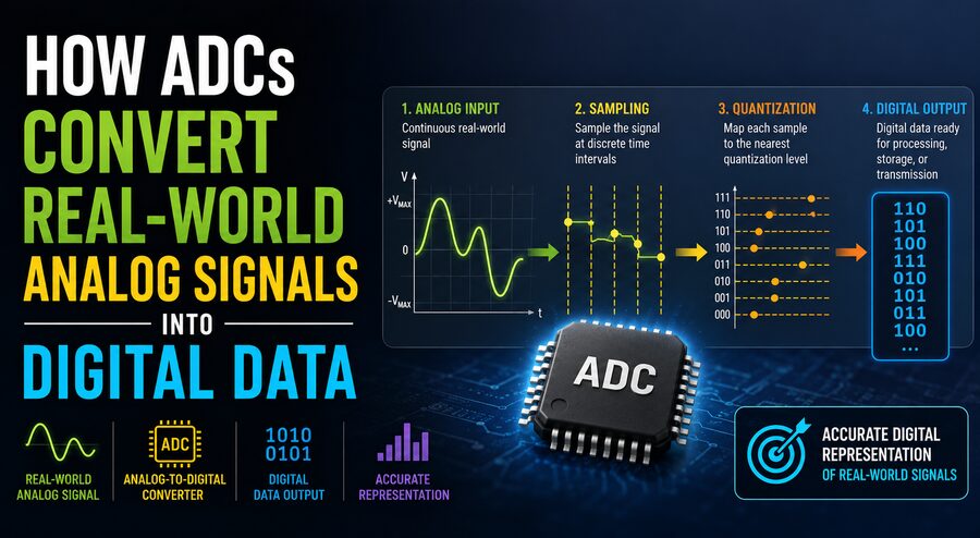
The conversion process generally involves three major ideas:
sampling, quantization, and encoding.
Together, these steps transform a continuously changing physical signal into a sequence of digital measurements. 🔢
⏱️ Step 1: Sampling the Analog Signal
The first step is called sampling.
An ADC does not usually measure an analog signal continuously. Instead, it takes measurements at specific moments in time.
Imagine photographing a moving object repeatedly.
Each photograph captures the object’s position at one instant.
Similarly, an ADC takes snapshots of an analog voltage.
For example:
Time       Voltage
0 ms       1.20 V
1 ms       1.65 V
2 ms       2.10 V
3 ms       1.80 V
4 ms       1.35 V
Each measurement is called a sample.
The number of samples taken each second is called the sampling rate or sample rate.
A sampling rate of 10,000 samples per second is written as:
10 kS/s
A system taking one million samples per second may be described as:
1 MS/s
The required sampling rate depends on how quickly the original analog signal changes.
🎵 Why Sampling Rate Matters
If an ADC samples too slowly, important details in the signal can be missed.
Consider recording a rapidly changing audio waveform.
If measurements are taken only occasionally, the digital representation may no longer resemble the original sound.
A fundamental principle called the Nyquist sampling theorem states that, under ideal conditions, the sampling frequency must be greater than twice the highest frequency contained in the signal if the signal is to be reconstructed correctly.
For example, if the highest relevant signal frequency is:
10 kHz
the sampling rate must be greater than:
20 kHz
in an idealized system.
Real systems typically use additional margin and filtering.
This is one reason digital audio uses relatively high sampling rates. 🎧
⚠️ What Is Aliasing?
If a signal is sampled too slowly, a phenomenon called aliasing can occur.
Aliasing causes high-frequency signals to appear incorrectly as lower-frequency signals in the digital data.
Once aliasing has entered the sampled data, it can be difficult or impossible to remove afterward.
To prevent this problem, ADC systems often use an anti-aliasing filter before the converter.
This is usually a low-pass filter that removes frequencies above the useful measurement range. 🎚️
The signal chain may therefore look like:
Sensor → Filter → ADC → Processor
The filter ensures that unwanted high-frequency components do not distort the digital measurements.
📏 Step 2: Quantization
After sampling, the ADC must assign each measured voltage to one of a limited number of digital levels.
This process is called quantization.
Suppose an ADC can measure from:
0 V to 5 V
and has only four possible output levels.
The entire voltage range must be divided into four sections.
An input near 0.5 V might be assigned one digital value, while an input near 4.5 V would be assigned another.
The ADC cannot represent every possible voltage exactly.
Instead, it chooses the closest available digital level.
This unavoidable approximation produces quantization error.
🔢 What Does ADC Resolution Mean?
The number of digital levels available depends on the ADC’s resolution.
Resolution is usually expressed in bits.
An 8-bit ADC can produce:
2⁸ = 256 levels
A 10-bit ADC can produce:
2¹⁰ = 1,024 levels
A 12-bit ADC can produce:
2¹² = 4,096 levels
A 16-bit ADC can produce:
2¹⁶ = 65,536 levels
Higher resolution means the input range is divided into smaller steps, allowing the ADC to distinguish smaller voltage differences. 📊
For an ideal N-bit ADC:
Number of levels = 2ᴺ
🧮 Example of ADC Resolution
Suppose a 12-bit ADC measures voltages between:
0 V and 3.3 V
It has:
4,096 possible levels
The approximate voltage represented by one step is:
3.3 V ÷ 4096 ≈ 0.000806 V
or approximately:
0.806 mV per step
This means the converter can theoretically distinguish voltage changes of roughly eight-tenths of a millivolt.
A higher-bit ADC would divide the same voltage range into even finer steps.
🎯 Step 3: Encoding the Measurement
After quantization, the ADC converts the selected level into a binary number.
Suppose an 8-bit converter measures a voltage corresponding to digital value:
182
In binary, that becomes:
10110110The processor receives this digital code and can then perform calculations with it.
For example, software may convert that value into:
- temperature in °C,
- pressure in pascals,
- light level,
- battery voltage,
- microphone amplitude.
This is the final step that turns an analog measurement into usable digital data. 💻
🧊 What Is a Sample-and-Hold Circuit?
An analog voltage may continue changing while the ADC is performing a conversion.
To obtain an accurate measurement, many ADC systems use a sample-and-hold circuit.
This circuit briefly captures the input voltage and holds it approximately constant while the ADC determines its digital value.
It is similar to freezing a moving image so it can be measured precisely. 📸
Without this function, rapidly changing signals could create errors during conversion.
In many modern integrated ADCs, sample-and-hold circuitry is built directly into the converter.
⚙️ Different Types of ADCs
Not all ADCs work internally in the same way.
Engineers choose different architectures depending on required speed, accuracy, power consumption, and cost.
🚀 Flash ADC
A flash ADC is extremely fast.
It compares the input voltage with many reference levels simultaneously using multiple comparators.
Because many comparisons happen at once, flash ADCs can perform conversions very quickly.
They are useful in applications such as:
- high-speed communications,
- radar,
- fast oscilloscopes,
- video systems.
The disadvantage is that high-resolution flash ADCs require many comparators, increasing circuit complexity and power consumption. ⚡
🔍 Successive Approximation ADC
A Successive Approximation Register ADC, or SAR ADC, is widely used in microcontrollers, sensors, and embedded systems.
It determines the input value using a process similar to binary search.
The ADC first tries a value near the middle of its range.
It then determines whether the actual input is higher or lower.
Each subsequent comparison narrows the possibilities.
For an N-bit SAR ADC, roughly N comparison steps can determine the final digital value.
SAR converters offer an excellent balance of:
- speed,
- resolution,
- power consumption,
- cost.
This makes them extremely common in electronics. 🔧
🎚️ Sigma-Delta ADC
A sigma-delta ADC uses oversampling, feedback, and digital filtering to achieve very high resolution.
These converters are especially useful when extremely precise measurements are required but ultra-high conversion speed is not essential.
Common applications include:
- high-quality audio,
- precision instruments,
- weighing scales,
- industrial sensors,
- scientific measurements.
Sigma-delta ADCs can achieve excellent noise performance and high effective resolution. 🎵🔬
⏳ Dual-Slope ADC
A dual-slope ADC measures an input over a relatively long time period and compares it against a known reference.
It is slower than many other ADC architectures, but it can provide excellent accuracy and rejection of certain types of electrical noise.
Dual-slope ADCs are commonly associated with digital multimeters. 🔧📟
Their slower conversion is acceptable because a handheld meter does not usually need millions of measurements per second.
📐 Reference Voltage: The ADC’s Measuring Ruler
An ADC requires a reference voltage to determine the relationship between analog voltage and digital code.
The reference acts like the ruler used to measure the incoming signal.
Suppose an ADC has:
- minimum input: 0 V,
- reference voltage: 5 V.
An input near half the reference voltage would produce a digital code near the middle of the available range.
If the reference voltage changes unexpectedly, the ADC measurements also change.
Therefore, precision measurement systems often use highly stable voltage-reference circuits.
A noisy or unstable reference can reduce overall measurement accuracy even when the ADC itself is very good. 📏
🌫️ Noise Can Affect ADC Measurements
Real electronic systems contain electrical noise.
Noise can come from:
- switching power supplies,
- motors,
- radio signals,
- digital circuits,
- thermal effects,
- electromagnetic interference,
- poor grounding.
If the analog signal is small, noise may significantly change the measured value.
Engineers therefore use methods such as:
- filtering,
- shielding,
- proper PCB layout,
- differential measurements,
- averaging,
- stable references.
In precision systems, the quality of the analog signal entering the ADC can be just as important as the converter itself. 🛡️
📉 ADC Accuracy Is More Than Bit Resolution
A high-bit-count ADC is not automatically highly accurate.
For example, a 16-bit converter may theoretically provide 65,536 levels, but real-world imperfections can prevent all those levels from representing perfectly accurate measurements.
ADC specifications may include:
- offset error,
- gain error,
- integral nonlinearity,
- differential nonlinearity,
- noise,
- effective number of bits,
- signal-to-noise ratio.
These parameters describe how closely the real converter behaves compared with an ideal ADC.
Engineers must consider both resolution and accuracy when selecting a converter.
🎤 ADCs in Digital Audio
Microphones produce analog electrical signals.
Before a computer or smartphone can record the sound, an ADC converts the microphone waveform into a stream of numbers.
For example:
Microphone → Preamplifier → Anti-Aliasing Filter → ADC → Digital Audio Data
Thousands of samples are taken every second.
Each sample records the amplitude of the sound waveform at a particular instant.
These numbers can then be stored in an audio file, processed with software, transmitted over the internet, or played back later through a digital-to-analog converter. 🎧
📷 ADCs in Digital Cameras
Camera sensors also depend heavily on analog-to-digital conversion.
When light strikes the pixels of an image sensor, each pixel generates an electrical signal related to the amount of light received.
These analog signals are converted into digital values.
The numbers eventually become pixel brightness and color information.
Millions of ADC measurements may contribute to a single photograph. 📸
The camera’s image processor can then apply operations such as:
- color correction,
- noise reduction,
- sharpening,
- exposure adjustment,
- compression.
Without analog-to-digital conversion, modern digital photography would not be possible.
🌡️ ADCs in Sensors and Embedded Systems
Microcontrollers frequently include built-in ADCs.
Suppose a temperature sensor outputs:
10 mV per degree Celsius
A microcontroller can measure that voltage using its ADC and calculate the temperature.
Similarly, ADCs can measure:
- battery voltage 🔋,
- joystick position 🎮,
- pressure sensors,
- soil moisture 🌱,
- light sensors 💡,
- potentiometers,
- current sensors ⚡.
This makes ADCs essential in embedded electronics and the Internet of Things.
🚗 ADCs in Modern Vehicles
Cars contain many analog sensors whose signals must be interpreted digitally.
ADCs may help measure:
- throttle position,
- battery voltage,
- engine temperature,
- pressure,
- oxygen-sensor outputs,
- steering position,
- accelerometer signals.
The electronic control unit uses these measurements to make decisions about engine control, braking, safety, battery management, and other vehicle functions. 🚘⚙️
Accurate analog-to-digital conversion is therefore an important part of automotive electronics.
🏥 ADCs in Medical Equipment
Many biological signals are extremely small and analog in nature.
An electrocardiogram, or ECG, measures tiny electrical voltages produced by the heart. ❤️
Medical electronics amplify and filter these signals before sending them to high-quality ADCs.
The digital data can then be:
- displayed,
- recorded,
- analyzed,
- transmitted,
- used by diagnostic software.
Similar principles apply to electroencephalography, blood-pressure monitors, pulse sensors, and many laboratory instruments.
Because medical signals can be small, noise control and ADC accuracy are especially important.
🔄 ADC vs. DAC
An ADC performs:
Analog → Digital
A Digital-to-Analog Converter, or DAC, performs the reverse operation:
Digital → Analog
For example, when recording music:
Microphone → ADC → Digital File
When playing that music:
Digital File → DAC → Amplifier → Speaker
🎤➡️🔢➡️🎵➡️🔊
Many electronic devices contain both ADCs and DACs because they need to communicate with both the digital world and the physical world.
🧠 Why ADCs Are So Important
Modern computing would be far less useful if computers could not measure physical signals.
The real world does not naturally arrive as binary numbers.
Temperature, sound, light, pressure, and motion exist as continuous physical quantities.
ADCs provide the bridge.
They sample a signal at specific moments, quantize each measurement into one of a finite number of levels, and encode the result as a digital number.
Once the measurement becomes digital, software can perform enormous amounts of processing on it. 💻✨
🌍 From Physical Reality to Binary Numbers
An Analog-to-Digital Converter is one of the fundamental technologies that allows electronics to interact with the real world.
The process begins with an analog signal from a microphone, sensor, camera, instrument, or other device. The ADC measures that signal repeatedly, assigns each measurement to a digital level, and outputs a binary number representing the result.
Sampling rate determines how frequently the signal is measured. ⏱️
Resolution determines how finely its amplitude can be represented. 📏
Reference voltage establishes the measurement scale, while filtering, noise control, and careful circuit design help preserve accuracy.
Whether you are recording your voice, taking a photograph, checking your smartwatch, driving a modern car, or measuring temperature with a microcontroller, ADCs are quietly translating physical reality into numbers that computers can understand.
Their central purpose can be summarized simply:
ADCs turn continuously changing real-world electrical signals into discrete digital data that computers can store, process, analyze, and use for decisions. 🌍➡️⚡➡️🔢➡️💻