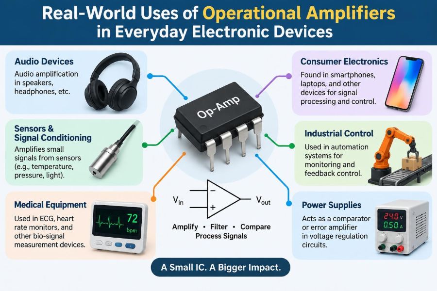

You turn up a speaker and the music becomes louder without turning into a harsh buzz. A phone charger decides when a battery is full. A bathroom scale converts a tiny bend in metal into a readable number. Behind these ordinary actions are circuits that must detect, compare, filter, or control electrical signals.
One of the most versatile building blocks for those jobs is the operational amplifier, usually shortened to op-amp. Although the name suggests a device used only for mathematical operations, op-amps appear throughout consumer electronics, appliances, instruments, vehicles, and industrial equipment.
An op-amp is rarely the whole product or even the most visible component on a circuit board. Its value comes from the way a designer surrounds it with resistors, capacitors, diodes, and feedback paths. Those few external parts can turn one small integrated circuit into a microphone preamplifier, a temperature alarm, or a precision sensor interface.
Understanding these real-world roles makes circuit diagrams less abstract. It also helps engineers and technicians recognize why an apparently simple analog circuit may behave unexpectedly when noise, power limits, or component tolerances are ignored.
🧠 What an Operational Amplifier Actually Does
An op-amp is a high-gain differential amplifier: it responds to the voltage difference between its two input terminals. The non-inverting input is marked +, and the inverting input is marked −.
In a basic model, the output follows Vout = A(V+ − V−), where A is open-loop gain. Since this gain is very large, even a tiny input difference would drive the output toward one supply rail if the op-amp were used without control.
That apparent limitation is what makes feedback so useful. By returning part of the output to an input, a designer sets a predictable gain or behavior.
🔁 Negative Feedback Makes Op-Amps Practical
Negative feedback feeds a fraction of the output back to the inverting input. The circuit then adjusts its output until the two input voltages are nearly equal, provided it is operating within its limits.
Rather than depending on the poorly controlled internal gain of the chip, the closed-loop gain depends mainly on external resistor ratios. This gives repeatable behavior and lets the same basic op-amp serve many roles.
For example, an inverting amplifier with input resistor Rin and feedback resistor Rf has an ideal gain of −Rf/Rin. The minus sign means the output signal is inverted.
📦 The Ideal Model Versus a Real Device
Introductory circuit analysis often treats an op-amp as ideal: infinite gain, infinite input resistance, zero output resistance, unlimited speed, and outputs that reach any voltage. Real components do none of these perfectly.
They have finite bandwidth, limited output current, input bias currents, offset voltage, noise, and a restricted input and output voltage range. A design that works in simulation under ideal assumptions may fail on a breadboard if these details are not checked.
The right approach is not to distrust op-amps. It is to match the device specifications to the signal level, frequency, supply voltage, load, and required accuracy.
🎙️ Microphone Preamplifiers in Audio Equipment
A microphone produces a small voltage that usually cannot directly drive the next stages of an audio system. An op-amp preamplifier boosts that signal to a more useful level while aiming to add as little noise and distortion as practical.
In a podcast interface, smart speaker, intercom, or mixer, the first amplifier stage matters greatly. Noise introduced there is amplified along with the wanted sound by later stages.
Audio designers choose low-noise devices and sensible resistor values, then provide adequate headroom so loud speech or music does not clip at the supply rails.
🔊 Active Filters Shape Sound in Speakers
Op-amps are widely used in active filters, which pass selected frequencies and reduce others. A tone control can emphasize bass or treble, while an equalizer divides audio into adjustable frequency bands.
Powered speakers and active crossover networks use filters to send low-frequency content to a woofer and higher-frequency content to a tweeter. This avoids asking each driver to reproduce frequencies it handles poorly.
Unlike a purely passive filter, an active filter can provide gain and buffering. It does, however, require power and must be designed to avoid overload from strong signals.
🎛️ Buffer Stages Prevent Signal Loading
A source circuit can be disturbed when it is connected to a load with relatively low input resistance. This is called loading; it can reduce the signal voltage and alter frequency response.
An op-amp configured as a voltage follower has a gain near one: its output is connected to its inverting input. It presents high input impedance to the source and low output impedance to the load.
Buffers are found between sensor circuits, control knobs, filter stages, analog-to-digital converters, and audio sections. They do not make a signal larger, but they make it easier to pass along reliably.
⚖️ Comparators and Threshold Decisions
An op-amp can be used without negative feedback to compare two voltages. The output moves high or low depending on which input is greater. This supports simple decisions such as “is the battery voltage above a limit?”
Dedicated comparators are often a better choice for fast or logic-facing threshold circuits because they are designed to switch rapidly and recover cleanly from saturation. Still, low-speed op-amp comparator arrangements appear in many basic products.
Typical uses include low-battery indicators, water-level alarms, light-activated lamps, and over-temperature warning circuits.
🪜 Hysteresis Stops Flickering and Chatter
A threshold circuit can misbehave when its input is noisy or hovers close to the switching point. A light sensor near dusk, for example, may make a lamp rapidly turn on and off if it uses one exact threshold.
Hysteresis solves this by using two thresholds. The circuit might turn the lamp on at one lower light level and leave it on until the environment becomes noticeably brighter.
Positive feedback creates this small memory effect in a comparator circuit. It is a practical reminder that real signals often contain noise, ripple, and slow transitions.
🌡️ Temperature Monitoring and Fan Control
Temperature sensors may produce a voltage related to temperature, while thermistors change resistance as temperature changes. An op-amp can amplify, buffer, filter, or compare these sensor signals.
In a simple fan controller, a comparator may switch a transistor or control input once a heat sink reaches a selected temperature. More refined versions use analog feedback to vary fan speed gradually rather than switching abruptly.
Sensor placement matters as much as circuit design. A perfectly calibrated circuit cannot protect a hot component if the sensor is mounted where it responds too slowly.
🔋 Battery Chargers and Power Monitors
Charging systems need voltage and sometimes current measurements to determine the state of a battery and to regulate charging safely. Op-amps commonly amplify the small voltage across a current-sense resistor or compare a battery voltage with a reference.
In many modern products, a specialized battery-management IC performs much of the charging algorithm. Op-amp principles still exist inside or around these circuits, especially in feedback loops and current measurement paths.
Battery chemistry imposes strict limits. An op-amp circuit is not, by itself, a universally safe charger; the control method must match the battery type and the manufacturer’s charging requirements.
📏 Current Sensing in Everyday Power Circuits
To measure current, a circuit can place a small resistor in the current path and measure its voltage drop. Because that drop may be only millivolts, amplification is often required before a controller or meter can use it.
A differential op-amp arrangement rejects voltage common to both measurement leads and emphasizes their small difference. This is useful in power adapters, LED drivers, motor controllers, and electronic loads.
Resistor placement is critical. High-side sensing observes current near the positive supply, while low-side sensing is simpler in some designs but lifts the load above ground by the sense voltage.
💡 LED Dimmers and Constant-Current Drivers
LED brightness is primarily controlled by current, not simply by applied voltage. An op-amp can compare the voltage across a sense resistor with a reference and adjust a transistor or switching-controller input to regulate current.
This feedback principle helps compensate for changes in supply voltage and LED forward voltage. In an analog dimmer, changing the reference changes the target current.
Many efficient high-power LED drivers use dedicated switching regulators rather than a standalone linear op-amp circuit. Even then, error amplifiers and feedback concepts remain central to regulation.
⚡ Power-Supply Feedback Regulation
A regulated power supply compares its output with a reference and corrects any difference. If the output begins to fall under load, the control loop requests more energy transfer; if it rises too high, the loop reduces it.
An op-amp or an amplifier-like error stage supplies this comparison function. In linear regulators it may directly control a pass transistor; in switch-mode supplies it influences the switching duty cycle or current command.
Feedback loop stability is essential. An unstable supply can oscillate, creating output ripple, audible noise, overheating, or unreliable behavior rather than steady regulation.
📱 Signal Conditioning Before an ADC
Microcontrollers measure analog voltages using an analog-to-digital converter (ADC). Sensors rarely deliver an ideal signal range directly, so an op-amp is often used to condition the signal first.
Conditioning may include amplification, level shifting, buffering, and low-pass filtering. A sensor producing a small voltage swing can be scaled to use more of the ADC range, improving usable measurement resolution.
The op-amp output must remain within the ADC input limits. A circuit that produces a negative output or exceeds the ADC reference can give incorrect readings and may damage an unprotected input.
🏋️ Strain Gauges in Scales and Force Sensors
Electronic scales use load cells containing strain gauges, resistive elements whose resistance changes slightly when metal flexes. These gauges are commonly arranged as a bridge that produces a very small differential voltage.
An instrumentation amplifier, often built from op-amp stages or supplied as a dedicated IC, amplifies this signal while rejecting interference common to both input leads. Its high input impedance prevents the bridge from being heavily loaded.
Accurate weighing also requires calibration, mechanical stability, and compensation for drift. Amplification alone cannot distinguish a real load change from every environmental effect.
🩺 Biomedical and Wearable Sensor Front Ends
Wearables and medical instruments can measure weak biological signals or sensor outputs, such as optical photodiode currents or electrode voltages. Their front ends use carefully selected amplifiers to preserve tiny signals while controlling noise and interference.
These applications need more than high gain. Input protection, filtering, isolation, electrode behavior, motion artifacts, and patient safety all affect the final system.
For safety-critical equipment, a classroom circuit should never be treated as a clinical design. Applicable standards, validation, and professional engineering processes are necessary.
📷 Photodiode Amplifiers in Light Sensors
A photodiode generates a current when light reaches it. A transimpedance amplifier uses an op-amp and feedback resistor to convert that current into a voltage.
This arrangement appears in automatic brightness sensors, optical receivers, barcode scanners, smoke-detection optics, and laboratory instruments. The feedback resistor sets sensitivity, while a small feedback capacitor may control high-frequency stability.
Ambient light, diode capacitance, and leakage currents can influence performance. A light sensor intended for sunlight measurement needs different range and protection choices from one inside a dim indoor device.
🧼 Appliance Sensors and Safety Interlocks
Washing machines, coffee makers, air conditioners, and other appliances must interpret water level, temperature, pressure, or current signals. Op-amp stages can amplify those signals and generate threshold decisions for a controller.
For example, a pressure sensor may help estimate water level, while a current-sense circuit can help identify a stalled motor. The resulting action is usually handled by a microcontroller, relay driver, or power transistor.
Safety functions should not depend casually on a single analog threshold. Designers account for failed sensors, broken wires, supply faults, and conditions that could make an apparently normal reading misleading.
🚗 Automotive Signal Interfaces
Vehicles contain many electrical sensors: pressure, temperature, position, current, and speed-related sensors. Their outputs often require filtering and scaling before a control module processes them.
Automotive electrical systems are harsh. Supply disturbances, load dumps, long cable runs, electromagnetic interference, and temperature extremes affect amplifier selection and circuit protection.
An op-amp suited to a quiet indoor audio device may be unsuitable for a vehicle. Input range, transient tolerance, operating temperature, and fault behavior must be considered as a system.
📡 Communication Circuits and Signal Filtering
At low and moderate frequencies, op-amp filters help remove unwanted noise or restrict a signal to a useful band. A communications interface may use a low-pass filter before digitization to reduce high-frequency content that could alias into the measured band.
Op-amps can also buffer reference voltages and provide gain in baseband signal paths. At radio frequencies, however, ordinary general-purpose op-amps are often too slow, and specialized RF components are used instead.
The lesson is that “amplifier” does not automatically mean “works at every frequency.” Bandwidth and stability remain design constraints.
🧮 Analog Computing and Control Loops
The name operational amplifier comes from analog computers, where resistor-capacitor networks around op-amps performed addition, subtraction, integration, and differentiation. Those functions remain useful in practical control systems.
An integrator accumulates an input over time; a differentiator responds to the rate of change. Variations of these behaviors appear in compensators that help a motor, heater, or power supply reach a target smoothly.
Modern controllers are frequently digital, but analog conditioning and compensation still offer fast, simple responses in the right application.
🧪 Test Equipment and Bench Instruments
Multimeters, function generators, oscilloscopes, and laboratory power supplies use op-amps in input amplifiers, buffers, active filters, reference circuits, and feedback controls. A measurement instrument is essentially a carefully managed signal path.
For a multimeter, the input stage may scale and protect a voltage before conversion. In a bench supply, an error amplifier compares actual output voltage or current with the user’s setting.
Accuracy depends on the entire chain: resistor tolerance, voltage reference stability, amplifier offset, layout, calibration, and temperature behavior all contribute.
🎮 Joysticks, Knobs, and Human Controls
Potentiometers in joysticks, volume controls, and adjustment knobs can produce noisy or imperfect voltages. Op-amp buffers and filters make those control signals more robust before they reach an ADC or control circuit.
A small low-pass filter can prevent a rapidly changing reading caused by contact noise from making a menu jump erratically. Excessive filtering, though, creates noticeable lag.
Design is therefore a trade-off between responsiveness and stability. The best setting depends on whether the signal represents a fast action, such as steering, or a slow adjustment, such as a thermostat setpoint.
📉 Offset, Drift, and Small-Signal Accuracy
An op-amp may output a small error even when its two inputs are at the same voltage. This input offset voltage becomes significant when measuring millivolt-level signals or using very high gain.
Temperature can change offset, bias current, and resistor values over time. This gradual change is called drift, and it can cause a precision sensor reading to move even when the physical quantity remains unchanged.
Chopper-stabilized or auto-zero amplifiers can reduce offset and drift in suitable applications, though they may introduce switching artifacts that need filtering.
🌪️ Noise, Grounding, and PCB Layout
A well-chosen op-amp cannot rescue a poorly laid out circuit board. Long high-impedance traces can pick up interference, shared ground paths can inject load current noise, and switching regulators can couple ripple into sensitive analog inputs.
Useful habits include keeping feedback paths short, placing supply decoupling capacitors close to the device, separating noisy power paths from low-level sensor traces, and planning a sensible return-current path.
Shielding and twisted-pair wiring can help with remote sensors, but they are not substitutes for appropriate filtering and a sound grounding strategy.
🚧 Supply Rails and Input-Output Limits
A common beginner error is assuming an op-amp powered from 5 V can accept any signal between 0 V and 5 V and produce the same range at its output. Many devices cannot.
Rail-to-rail input means the input common-mode range extends close to both supply rails; rail-to-rail output means the output can swing close to them under stated load conditions. These are separate specifications.
Always check the data sheet for input common-mode range, output swing, supply range, and output-current limits. “Close to a rail” is not the same as exactly reaching it.
🏃 Speed, Slew Rate, and Stability
Bandwidth describes how gain falls as frequency rises. Slew rate describes the maximum rate at which an output voltage can change. A circuit can have enough small-signal bandwidth yet still distort a large, fast waveform because the output cannot move quickly enough.
Capacitive loads, such as long cables or some ADC inputs, can also destabilize an op-amp. The result may be oscillation that is invisible without an oscilloscope but disruptive to measurements and power consumption.
Compensation components, output isolation resistors, and devices rated for the required gain and load are common solutions.
🛠️ A Practical Op-Amp Selection Checklist
Choosing an op-amp begins with the job, not with a familiar part number. A low-noise audio stage, a micropower battery sensor, and a fast photodiode receiver have very different priorities.
- Check the available supply voltage and whether a single-supply circuit is required.
- Confirm input common-mode range and output swing over the intended load.
- Estimate required gain, signal bandwidth, and slew rate.
- Consider offset, bias current, noise, and drift for the expected signal level.
- Verify output current, capacitive-load behavior, package, temperature range, and quiescent current.
Data-sheet graphs and application notes often reveal behavior not obvious from the headline specifications.
🔍 Troubleshooting an Op-Amp Circuit Systematically
When an op-amp circuit fails, start with the basics: measure the supply rails at the IC pins, confirm the ground reference, and check that inputs are within their allowed range. A missing or reversed supply is more common than an exotic analog fault.
Then inspect the feedback network, resistor values, component orientation, and load. If the output is stuck near a rail, determine whether the input differential voltage demands that state or whether the device has exceeded an operating limit.
An oscilloscope is especially useful for finding oscillation and noise. Measuring only a steady average voltage can hide a high-frequency instability.
🧩 The Core Principle Behind Everyday Op-Amp Uses
Across audio equipment, chargers, sensors, appliances, and instruments, the recurring pattern is simple: an op-amp senses a difference and uses a carefully designed network to produce a useful response.
Sometimes that response is a larger voltage, sometimes a filtered signal, a threshold decision, or a correction command in a feedback loop. The surrounding circuit defines the job; the op-amp supplies controlled amplification and comparison.
Its flexibility does not eliminate engineering limits. Good designs respect signal range, frequency response, noise, stability, power constraints, and the consequences of failure.
Operational amplifiers matter because they translate weak, messy, real-world electrical signals into controlled information and action. Once that pattern is clear, many everyday electronic devices become easier to understand—and easier to design or troubleshoot. 🔌📏⚙️