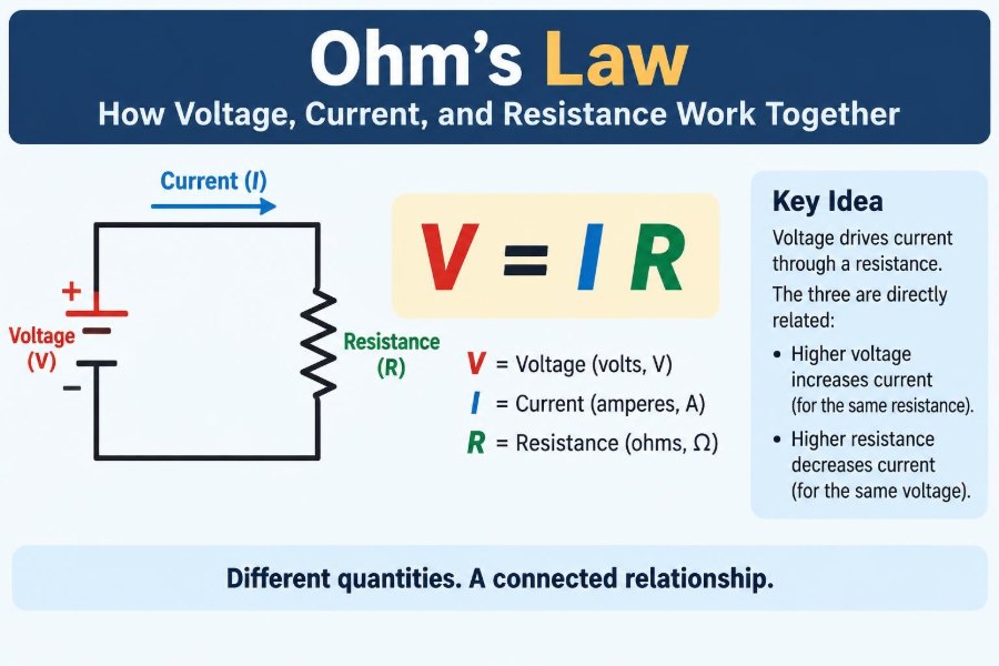

A phone charger warms slightly while replenishing a battery. A lamp becomes dimmer when its supply voltage falls. A circuit breaker opens when too much current flows through a wire. These familiar events are all connected by one compact relationship: Ohm’s law.
The formula is simple enough to fit on a sticky note, yet using it well requires more than rearranging three letters. You need to know what voltage, current, and resistance mean physically, where they are measured, and which assumptions make the calculation valid.
For students, Ohm’s law is often the first reliable tool for analyzing a circuit. For technicians and engineers, it remains a quick way to estimate component stress, trace faults, choose resistor values, and check whether a measured result is plausible.
Understanding how the three quantities work together turns a circuit from a collection of symbols into a system with predictable behavior.
⚡ Ohm’s Law in One Equation
Ohm’s law states that, for an ohmic component under stable physical conditions, voltage across the component equals current through it multiplied by its resistance:
V = I × RHere, V is voltage in volts (V), I is current in amperes (A), and R is resistance in ohms (Ω). The equation says that a larger resistance needs a larger voltage to drive the same current, while a larger voltage drives more current through the same resistance.
It does not mean that voltage “turns into” current or that resistance consumes current. These quantities describe different aspects of electrical behavior, and their relationship depends on the device and conditions involved.
🔋 Voltage Is Electrical Potential Difference
Voltage is the difference in electric potential between two points. It represents the energy transferred per unit of electric charge as charge moves between those points.
A battery marked 9 V maintains approximately nine volts of potential difference between its terminals under suitable conditions. That voltage provides the push that can move charge when a complete path exists.
The word difference matters. Voltage is always measured between two locations, such as across a resistor, from a supply rail to ground, or between the terminals of a battery. A single point does not possess voltage in isolation; it has a voltage relative to a chosen reference.
🌊 Current Is the Flow of Electric Charge
Current is the rate at which electric charge passes a point in a circuit. One ampere equals one coulomb of charge passing per second.
In a metal wire, the mobile charge carriers are electrons. By long-standing convention, circuit diagrams show conventional current flowing from higher potential toward lower potential, from the positive supply terminal toward the negative terminal. Electron motion in metals is in the opposite direction.
Both descriptions can be used consistently, but introductory circuit analysis normally follows conventional current. The important practical point is that current requires a closed path. An intact battery connected to an open switch has voltage available, but essentially no current flows in that branch.
🧱 Resistance Opposes Current Flow
Resistance describes how strongly a component opposes the flow of current. A resistor intentionally provides a known resistance, but wires, connectors, switches, batteries, motors, and semiconductor devices also have resistance.
At the microscopic level, moving charge carriers in a material interact with atoms, impurities, and structural features. These interactions make charge movement harder and, in many materials, convert electrical energy into thermal energy.
A high resistance does not stop current under every condition. It means that more voltage is required to produce a given current. Conversely, a very low resistance can permit a large current if the source and wiring can supply it.
🔺 The Useful Ohm’s Law Triangle
A familiar memory aid places V at the top of a triangle and I and R at the lower corners. Cover the quantity you want to find: the remaining arrangement suggests the formula.
- To find voltage:
V = I × R - To find current:
I = V ÷ R - To find resistance:
R = V ÷ I
The triangle can help with recall, but it should not replace units or reasoning. If a calculation predicts tens of amperes through a tiny signal resistor, the arithmetic may be correct while the proposed circuit is unsafe or impractical.
📏 Units That Keep Calculations Honest
Using standard units makes Ohm’s law self-checking. Voltage is measured in volts, current in amperes, and resistance in ohms. If volts are divided by ohms, the result is amperes.
| Quantity | Symbol | Base unit | Common prefixes |
|---|---|---|---|
| Voltage | V | volt (V) | mV, kV |
| Current | I | ampere (A) | µA, mA |
| Resistance | R | ohm (Ω) | Ω, kΩ, MΩ |
Prefixes are a frequent source of errors. A 2.2 kΩ resistor is 2,200 Ω, while 2.2 MΩ is 2,200,000 Ω. Similarly, 25 mA is 0.025 A, not 25 A.
🧮 A First Calculation Example
Suppose a 12 V supply is connected across a 1 kΩ resistor. Convert the resistance first: 1 kΩ equals 1,000 Ω. Then apply Ohm’s law:
I = V ÷ R = 12 V ÷ 1,000 Ω = 0.012 A = 12 mAThe result is reasonable: a kilohm-scale resistor connected to a modest voltage usually produces a current in milliamperes, not amperes. This quick sense check becomes increasingly valuable as circuits become more complex.
🚰 The Water Analogy—and Its Limits
A water system can offer a helpful first picture. Voltage resembles pressure difference, current resembles the rate of water flow, and resistance resembles a restriction in a pipe. Greater pressure can push more water through the same restriction; a narrower restriction reduces flow for the same pressure.
However, electricity is not literally water. Electric charge does not get used up as it passes through a resistor, and electrical fields establish circuit behavior far more quickly than individual electrons drift through a wire. The analogy is useful for intuition, not a complete physical model.
🔌 A Closed Loop Is Essential
To sustain current, a circuit needs a complete conductive loop from one supply terminal, through the load, and back to the other terminal. The supply establishes an electric field around the loop that drives charge carriers already present in the conductors.
If a switch opens the loop, current falls to nearly zero in that path. The voltage may then appear across the open switch rather than across the load, depending on the circuit arrangement.
This distinction explains why measuring voltage alone does not prove that a device is operating. A disconnected wire may show a supply voltage with a high-impedance meter, yet carry no useful current.
🧭 Polarity and Sign Conventions
Voltage and current have assigned reference directions. A resistor may be labelled with a positive voltage reference at one end and a negative reference at the other. If conventional current enters the marked positive end, the resistor follows the passive sign convention and absorbs power.
If your solved voltage or current is negative, the circuit has not necessarily failed. It usually means the real direction is opposite to the direction you assumed.
Being explicit about references prevents confusion in larger circuits. It also makes power calculations meaningful, because the signs indicate whether an element absorbs energy or delivers it.
🪨 What Makes a Material Resistive
The resistance of a uniform conductor depends on its material, length, and cross-sectional area. This relationship is commonly expressed as:
R = ρL ÷ AIn this expression, ρ (rho) is resistivity, a material property; L is conductor length; and A is cross-sectional area. Longer conductors generally have more resistance, while thicker conductors generally have less.
This is why long extension leads and thin wires can experience noticeable voltage drop when carrying substantial current. It is also why conductors selected for power distribution are much larger than wires used only for sensing signals.
🌡️ Temperature Changes Resistance
Ohm’s law is most straightforward when resistance stays approximately constant. In reality, many materials change resistance with temperature.
Most metal conductors have a positive temperature coefficient: their resistance rises as they heat. A tungsten lamp filament is a striking example. Its cold resistance is much lower than its operating resistance, so its switch-on current can be far higher than the current after it becomes hot.
Some materials and devices behave differently. Thermistors are designed so resistance changes strongly with temperature, and semiconductors have behavior that cannot always be represented by one fixed resistance. Treat calculated values as operating-point estimates when temperature is changing.
💡 Resistors Turn Electrical Energy into Heat
An ideal resistor obeys Ohm’s law and dissipates electrical energy mainly as heat. It does not store energy like a capacitor or inductor, and it does not generate energy like an active source.
Resistors are used to limit current, create voltage dividers, set amplifier gains, bias transistors, pull digital inputs to defined logic states, and sense current. Their apparent simplicity makes them foundational in nearly every electronic system.
Real resistors also have tolerance, maximum voltage, temperature coefficient, and power rating. A resistor’s printed resistance is only one part of selecting it properly.
🔥 Power Completes the Practical Picture
Ohm’s law tells you the relationship between voltage and current. Power tells you how quickly electrical energy is transferred or dissipated:
P = V × ICombining this with Ohm’s law produces two especially useful forms:
P = I²R
P = V² ÷ R
For the earlier 12 V, 1 kΩ example, the power is 0.144 W. A 0.25 W resistor may be suitable in a cool, well-ventilated application, but designers commonly allow margin rather than operate parts continuously at their rating limit.
⚠️ Why a Short Circuit Is Dangerous
A short circuit is an unintended very-low-resistance path between points at different voltages. With very little resistance to limit current, the current can become large enough to overheat conductors, damage a supply, vaporize conductive traces, or start a fire.
In a real circuit, current is limited by battery internal resistance, power-supply protection, wire resistance, contact resistance, and other factors. It is not mathematically infinite. That does not make it safe.
Never intentionally short a battery or bench supply to “see what happens.” Use current limiting, appropriate fuses, and safe equipment procedures, especially with high-energy batteries or mains-powered systems.
➕ Series Circuits Share One Current
Components in series are connected end to end, with no branching path between them. The same current flows through every component in that series path.
The total resistance is the sum of individual resistances:
Rtotal = R₁ + R₂ + R₃ + ...For example, 220 Ω and 330 Ω in series create 550 Ω. On a 5 V source, the current is approximately 9.1 mA, assuming the source and components behave ideally.
Each resistor has a voltage drop proportional to its resistance. This is the basis of voltage division.
➗ Parallel Circuits Share One Voltage
Components in parallel connect across the same two nodes. Each branch has the same voltage across it, while the total current is the sum of the branch currents.
For two resistors in parallel:
1 ÷ Rtotal = 1 ÷ R₁ + 1 ÷ R₂The equivalent resistance of parallel resistors is always lower than the smallest branch resistance. Adding another parallel path gives charge another route, so the source supplies more total current at the same voltage.
🎚️ Voltage Dividers Create Lower Voltages
A voltage divider uses two series resistors to produce an output voltage between the supply rails. If R₁ is connected to the positive supply and R₂ is connected to ground, the unloaded output at their junction is:
Vout = Vin × R₂ ÷ (R₁ + R₂)With equal resistor values, the output is half the input voltage. This is useful for reference voltages, sensor scaling, and signal conditioning.
There is a crucial limitation: a divider’s output changes if a load draws significant current from it. The load effectively becomes part of the lower resistance network. A divider is not automatically a stable power supply.
💻 LEDs Need Current Limiting
An LED is not a resistor with a fixed voltage-to-current relationship. Its current can rise sharply with a small change in applied voltage, so connecting it directly across a typical voltage source can damage it.
A series resistor limits current. For a hypothetical 5 V supply, a red LED with an approximate 2 V forward voltage, and a desired 10 mA current:
R = (5 V − 2 V) ÷ 0.010 A = 300 ΩIn practice, choose a standard value, account for supply tolerance and LED variation, and check resistor power. For higher-power LEDs, a constant-current driver is often more appropriate than a resistor alone.
🔧 Measuring Voltage Correctly
A digital multimeter measures voltage in parallel with the part or two circuit nodes of interest. Because a good voltmeter has high input resistance, it draws very little current and causes minimal disturbance in many low-frequency circuits.
Set the meter to the correct DC or AC voltage mode and an adequate range. Place the probes across the component, never in series merely to “look for voltage.”
Be careful around exposed energized conductors. Meter category ratings, probe condition, source voltage, and available fault current all matter. Consumer meters and leads are not interchangeable safety tools for every electrical environment.
🧪 Measuring Current Without Creating a Fault
An ammeter measures current in series, so the circuit path must be opened and routed through the meter. An ammeter has low internal resistance by design.
That low resistance is why placing a meter set to current mode directly across a voltage source can create a short circuit. It may blow the meter fuse, damage leads or equipment, or create a hazardous arc in high-energy situations.
- Turn off power before changing meter connections when practical.
- Use the correct current jack and range.
- Start on a higher range if the current is unknown.
- Move the lead back to the voltage jack after current measurements.
A clamp meter can measure current around a single conductor without opening the circuit, but its range and accuracy depend on the meter type and the current being measured.
🧷 Real Sources Have Internal Resistance
An ideal voltage source keeps the same voltage regardless of current. Real batteries and power supplies do not. They have internal resistance or more complex internal control behavior.
As load current rises, internal resistance causes a voltage drop inside the source. The terminal voltage available to the external circuit may fall. This is why a weak battery can appear acceptable with no load but fail to operate a motor or other demanding device.
A simple battery model uses an ideal voltage source in series with an internal resistance. It is not a complete model for every battery chemistry or supply, but it explains voltage sag and heating clearly.
📉 Voltage Drop in Wires and Contacts
Every conductor has some resistance. When current flows, the wire develops a voltage drop given by V = IR. At low current this may be negligible; at higher current or over long distances it can become a major design constraint.
Loose, corroded, or undersized connections add resistance. They can cause intermittent operation, dim lights, reduced motor torque, inaccurate sensor readings, and localized heating.
Fault-finding often involves measuring voltage drop under load. A connection that looks normal with power off may reveal its problem only when current is flowing through it.
📈 The Current-Voltage Graph of an Ohmic Resistor
For a resistor with constant resistance, a graph of current against voltage is a straight line passing through the origin. Doubling voltage doubles current; halving voltage halves current.
The graph’s slope depends on which variable is placed on each axis. On an I-versus-V graph, the slope is conductance, 1/R. On a V-versus-I graph, the slope is resistance.
Graphing measured values is a practical way to see whether a device is approximately ohmic over the range tested. Curvature indicates that resistance changes with voltage, current, temperature, or internal device state.
🚫 Devices That Do Not Strictly Obey Ohm’s Law
Ohm’s law is not a universal law stating that every electrical component has a fixed resistance. Diodes, LEDs, transistors, incandescent lamps, batteries, and many sensors have nonlinear current-voltage characteristics.
You can still calculate an effective or operating resistance at a particular point using R = V/I. But that value may not predict behavior at another voltage or temperature.
For nonlinear devices, engineers use datasheets, characteristic curves, equivalent models, and circuit simulation. Ohm’s law remains part of the analysis, particularly for resistors around the active device.
🔄 DC, AC, and the Difference Between Resistance and Impedance
For steady direct current (DC), resistance is often enough to describe a simple resistive circuit. Alternating current (AC) introduces another complication: capacitors and inductors oppose changing current and voltage in frequency-dependent ways.
The broader AC quantity is impedance, represented by Z and measured in ohms. Impedance includes resistance plus a reactive component associated with energy temporarily stored in electric or magnetic fields.
The familiar form V = IR can become V = IZ in AC analysis, often using complex numbers and phase angles. The basic intuition remains useful, but do not treat a capacitor or inductor as a fixed resistor in every AC situation.
🧠 Common Ohm’s Law Mistakes
Many errors are not failures of algebra; they are failures to identify the actual circuit condition. Watch for these common traps:
- Using resistor color bands or markings incorrectly, especially confusing kΩ with Ω.
- Forgetting that milliamperes must be converted to amperes in power calculations.
- Calculating only resistance and ignoring the resistor’s power rating.
- Assuming every device has a constant resistance.
- Applying a voltage-divider formula without considering the attached load.
- Connecting a current meter across a supply.
- Ignoring wire, connector, and source internal resistance in high-current circuits.
A disciplined sketch with labelled nodes, polarities, units, and expected current direction prevents many of these mistakes before any hardware is powered.
🛠️ A Reliable Problem-Solving Method
Use a consistent procedure rather than selecting a formula by habit. First, identify what is known and what must be found. Then decide whether the circuit is series, parallel, or a combination that needs simplification.
- Draw the circuit and label given values with units.
- Convert prefixes to compatible units.
- Find equivalent resistance if multiple resistors are involved.
- Apply Ohm’s law to find the needed voltage, current, or resistance.
- Calculate power for components that may dissipate significant energy.
- Check polarity, sign, magnitude, and component ratings.
Finally, compare the result to physical reality. A calculated current that exceeds a source rating or a calculated power above a component rating signals that the design needs revision, not that the component will somehow accommodate the number.
🧰 Designing with Margin Rather Than Bare Minimums
Real electronics must tolerate part variation, supply changes, ambient temperature, aging, and occasional abnormal conditions. A resistor chosen exactly at its predicted power dissipation may run hot and have little room for these effects.
Design margin can mean selecting a higher power rating, using a larger wire, limiting current at the source, or choosing components with suitable voltage ratings. The correct amount depends on the application, enclosure, cooling, reliability needs, and relevant safety requirements.
Margin is not an excuse for vague design. It follows from calculating expected conditions, identifying uncertainty, and selecting parts that remain within their specified limits.
🧩 A Practical Troubleshooting Example
Imagine a 12 V LED strip that is dim at the far end. A useful first question is whether the LEDs themselves are faulty or whether the supply voltage is dropping along the wiring.
Measure the source voltage and then measure voltage at the strip’s far end while it is operating. If the far-end voltage is lower, the cable and connections are likely contributing resistance. Ohm’s law connects the observed drop to the current and the resistance of that path.
The solution might be thicker wire, a shorter run, power injection at another point, or repaired connectors. Simply increasing supply voltage without understanding the strip’s rating can damage it, so diagnosis should come before modification.
🎯 The Core Principle to Remember
Ohm’s law links the electrical push across a component, the charge flow through it, and the opposition it presents. In its simplest form, increasing voltage increases current when resistance is constant; increasing resistance reduces current when voltage is constant.
Its real value comes from pairing the equation with circuit topology, units, power calculations, measurement practice, and awareness of non-ideal behavior. A resistor, a battery, a wire, and an LED can all appear in the same circuit, but they must not be modeled as identical kinds of components.
When you ask “where is the voltage measured, what path carries the current, and what limits that current?” the formula becomes a dependable engineering tool rather than a memorized rule.
Ohm’s law is simple because it captures a fundamental relationship, and powerful because careful engineers know exactly when—and how—to apply it. ⚡🔧📐