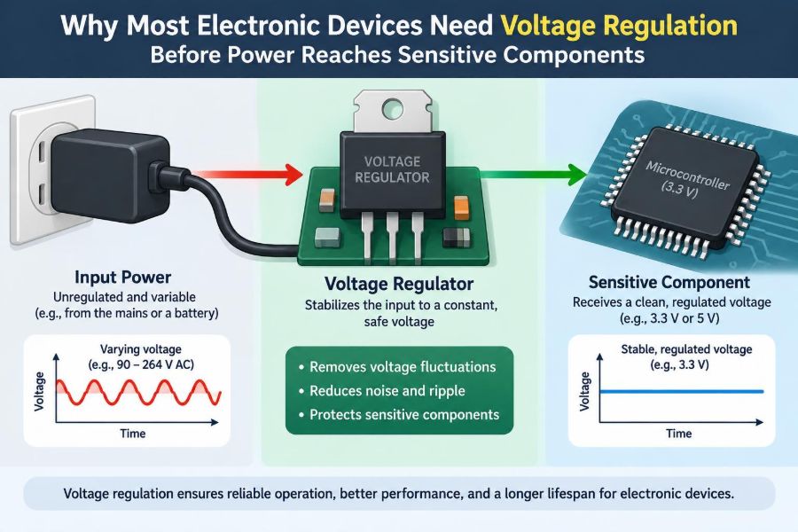

A phone charger can be rated at 5 V, yet the voltage arriving at a circuit is not automatically a perfect, motionless 5 V. Cable resistance, changes in load current, switching noise, connector quality, and the charger itself all influence what the electronics actually see.
The same issue appears in much larger systems. A car battery is called a 12 V source, but its voltage varies significantly between cranking, normal charging, and transient events. A wall adapter, solar panel, USB port, or lithium-ion cell may all be useful power sources while still being unsuitable for direct connection to a sensitive processor or sensor.
Most integrated circuits need a supply that stays within a defined operating range. Give them too little voltage and they may reset, calculate incorrectly, or fail to start. Give them too much, even briefly, and permanent damage can result.
This is why voltage regulation sits between a source of energy and the circuit that uses it. It is not an optional finishing touch in most designs; it is part of making electrical power predictable enough for electronics to trust.
⚡ A Power Source Is Not the Same as a Usable Supply
A power source provides electrical energy. A regulated supply provides energy at a controlled voltage under stated conditions. Those are different jobs.
A nominal label describes an intended or typical value, not necessarily the voltage at every instant and at every point in the circuit. A 9 V battery may begin above 9 V with almost no load and decline as it is discharged. A USB supply may be close to 5 V at its connector but lower at the far end of a thin cable carrying current.
Electronic components are designed around supply assumptions. Regulation converts a variable input into an output that better matches those assumptions.
🎯 What Voltage Regulation Actually Does
A voltage regulator compares its output with an internal reference and adjusts its behavior to reduce the difference. Its goal is to hold the output near a target value despite reasonable changes in input voltage, load current, and temperature.
For example, a regulator may accept an input that moves between 6 V and 12 V and produce 3.3 V for a microcontroller. It cannot create unlimited power, and it works only within its specified input, current, and thermal limits.
Regulation is therefore about control, not merely reducing voltage. A resistor can drop voltage in one situation, but it cannot actively maintain a chosen output as conditions change.
📏 Why Sensitive Components Have Narrow Limits
Modern ICs often use very small transistor structures. Their transistors switch according to voltage differences that may be only a fraction of a volt, so a supply shift can alter timing, logic thresholds, and analog measurements.
Data sheets normally distinguish among recommended operating voltage, absolute maximum ratings, and sometimes minimum retention or startup voltage. The absolute maximum rating is a damage boundary, not a sensible target for normal operation.
A 3.3 V device may tolerate only a limited amount above its intended rail. Connecting it casually to a 5 V supply can overstress input structures or internal transistors, even when the circuit seems to work at first.
🌊 Sources Naturally Produce Voltage Variation
Variation is a normal property of real sources, not evidence that a source is defective. Batteries change voltage with state of charge, temperature, age, and current draw. Solar modules change with illumination, temperature, and their connected load.
AC adapters can vary with mains conditions and loading. Generator-based sources can change with speed and load. Even another circuit board can create supply changes when a motor, radio transmitter, or display suddenly turns on.
Designers begin by asking for the full expected input range, including startup and fault-adjacent conditions, rather than designing around one label value.
🔋 Batteries Need Regulation Too
A battery-powered product is one of the clearest reasons to regulate voltage. A single lithium-ion cell has a voltage range that changes substantially through discharge, while many digital circuits expect a much tighter rail.
A linear low-dropout regulator, often called an LDO, can produce a stable lower rail while the battery remains sufficiently above that rail. A buck-boost converter can maintain a selected output even when the battery voltage moves above and below it.
The choice affects usable battery capacity. If a design uses only a simple regulator, it may have to shut down when the battery is still capable of delivering energy but no longer has enough voltage headroom.
🚗 Automotive Power Is a Demanding Example
Vehicle electrical systems contain alternators, inductive loads, long wire runs, and a battery shared by many subsystems. The supply line experiences normal variation as well as fast disturbances associated with switching loads and starting the engine.
An automotive electronic module generally needs more than a basic regulator. It may require input filtering, reverse-polarity protection, transient suppression, and a converter designed for its expected voltage range.
The exact requirements depend on the vehicle architecture and application. The engineering lesson is broader: a nominal 12 V line should not be treated as a clean 12 V laboratory rail.
🔌 Wall Power Starts as AC and Can Carry Disturbances
Equipment connected to mains power first has to convert AC into suitable DC. Rectification and bulk capacitors create a DC bus, but that bus is not automatically appropriate for low-voltage logic.
Offline power supplies use isolation and switching conversion to produce safer low-voltage outputs. Downstream regulators may still be used near processors, memory, sensors, and analog circuits because a 5 V adapter output is not identical to a quiet 1.0 V or 3.3 V local rail.
Mains-connected design has shock, fire, insulation, electromagnetic compatibility, and regulatory considerations. It should be approached with appropriate training and safety practices, not as a casual breadboard task.
📉 Voltage Drop in Wires Can Defeat a Good Supply
Every wire, trace, connector, fuse, and switch has resistance. When current flows, that resistance creates a voltage drop, approximated by V = I × R. The effect can be small at low current and severe in compact systems carrying several amperes.
Imagine a 5 V supply feeding a single-board computer through a long, thin cable. The supply may measure 5 V at its output while the board receives much less during a processing burst. The resulting resets can look like software problems.
Regulation near the load, adequate conductor size, short high-current paths, and sound connector choices help keep the voltage where it is needed.
📈 Loads Do Not Draw Constant Current
A load is rarely steady. A microprocessor can move from sleep to intense activity quickly. A radio may draw current pulses while transmitting. A motor driver, display backlight, or storage device can introduce abrupt demand changes.
When current rises, finite resistance and inductance in the power path can pull the rail downward. When current falls, stored energy in inductance can contribute to overshoot. The regulator and nearby capacitors must respond fast enough to keep the rail within limits.
This behavior is called load transient response. It is one reason a regulator data sheet specifies more than its output voltage and maximum current.
🧱 Capacitors Support, but Do Not Replace, Regulation
Capacitors store charge locally. A bypass or decoupling capacitor near an IC can supply brief current during a fast demand change and provide a short path for high-frequency noise.
However, a capacitor cannot hold a rail at the correct voltage indefinitely when the source is too high, too low, or changing slowly. Its voltage changes as charge enters or leaves it.
A robust power network uses both: regulation establishes the intended DC level, while capacitors help manage high-frequency behavior and transient current. Their placement, capacitance, equivalent series resistance, and parasitic inductance all matter.
🔄 Linear Regulators Trade Heat for Simplicity
A linear regulator controls output voltage by behaving like a variable electrical resistance. The voltage difference between input and output is converted largely into heat.
Its approximate dissipation is P = (VIN − VOUT) × IOUT. Although this expression is useful for intuition, thermal design must also account for package resistance, board copper, ambient temperature, and transients.
Linear regulators are often attractive for low-current rails, low-noise analog sections, or cases where the input is only slightly above the output. They are less suitable when a large voltage drop and significant current would create excessive heat.
⚙️ Switching Regulators Improve Efficiency
A switching regulator rapidly switches energy through inductors, capacitors, and semiconductor switches. Instead of continuously burning the input-to-output difference as heat, it transfers energy in controlled packets.
Common topologies include buck converters for step-down conversion, boost converters for step-up conversion, and buck-boost converters for inputs that may lie on either side of the output.
The efficiency advantage can greatly reduce battery drain and heating. The tradeoff is added circuit complexity, switching ripple, electromagnetic interference concerns, and a layout that must be treated as part of the electrical design.
🧭 Choosing Buck, Boost, or Buck-Boost
The input range relative to the required output is the first guide. A buck regulator requires input voltage above the desired output by an amount that depends on the device and operating conditions. A boost regulator produces an output above its input.
A buck-boost design is useful when a battery or other source crosses the intended output during normal use. For example, an output of 3.3 V from a single cell may call for buck-boost operation if the full cell-voltage range must be used.
| Converter type | Best basic fit | Typical example |
|---|---|---|
| Linear or buck | Input remains above output | 12 V source to 5 V rail |
| Boost | Input remains below output | Single cell to a higher LED rail |
| Buck-boost | Input can be above or below output | Battery rail to stable 3.3 V |
Topology selection is only the start. Current, ripple, startup behavior, cost, physical space, and noise sensitivity also shape the decision.
🔇 Regulation and Noise Are Related but Different
A regulator can maintain the correct average voltage yet still have output ripple or high-frequency noise. Conversely, a low-noise source can have the wrong DC voltage. Good power design evaluates both DC accuracy and AC behavior.
Switching converters create periodic ripple because of their operating method. Linear regulators can reject some input ripple, described by power-supply rejection ratio, but their rejection varies with frequency and operating conditions.
Precision analog amplifiers, data converters, clocks, and RF circuits may need especially clean rails. That can justify filters, carefully selected regulators, separate analog and digital power domains, or post-regulation after a switcher.
🧠 Digital Circuits Need Stable Timing Margins
Digital logic is often described as being tolerant because it recognizes high and low states rather than every intermediate voltage. In reality, supply voltage affects transistor switching speed, noise margin, and memory reliability.
If the voltage falls below a processor’s valid operating region, it may execute unpredictably before a reset circuit reacts. A properly designed brownout detector can place the system in reset or safe shutdown when the rail becomes too low.
Stable rails are especially relevant during boot, flash writes, and communications. These operations can fail in subtle ways when supply quality is poor.
🎛️ Analog Measurements Depend on Supply Behavior
Analog circuits respond to continuously varying voltages and currents, so supply imperfections can directly enter the signal path. A sensor interface may show apparent noise, offset, or drift if its reference and supply are poorly controlled.
An analog-to-digital converter often measures an input relative to a reference voltage. If that reference moves, the reported digital value can move even when the sensor output has not changed.
Not every analog circuit requires an ultra-low-noise supply. The needed performance depends on signal size, bandwidth, required accuracy, and whether supply variation is rejected or cancels in the measurement method.
💡 LEDs and Motors Need Current Control Consideration
Voltage regulation is central to many circuits, but it is not the whole story for every load. LEDs are primarily current-sensitive devices; a dedicated constant-current driver is often better than simply applying a regulated voltage and resistor, especially at higher power.
Motors can tolerate wider voltage variation than a microcontroller in some applications, but they create large startup currents and electrical noise. Their supply behavior can disturb nearby logic if both share an undersized path.
The practical approach is to regulate rails for sensitive electronics while designing load drivers and current paths specifically for the type of load involved.
🛡️ Regulation Is Not Surge Protection
A standard regulator is not automatically able to survive every overvoltage event. Input maximum ratings can be exceeded by reversed batteries, inductive kickback, incorrect adapters, or disturbances on external cables.
Protection may include fuses, resettable protectors, reverse-polarity circuits, transient-voltage suppressors, input filters, and carefully rated components. Which measures are appropriate depends on the environment and failure consequences.
Think of regulation as controlling expected variation. Think of protection as handling abnormal conditions and faults. Many reliable products need both.
🌡️ Thermal Limits Can Turn a Valid Schematic into a Failure
A circuit can be electrically correct and still overheat. A linear regulator dropping several volts at high current may enter thermal shutdown, reduce output capability, or suffer long-term stress if heat cannot escape.
Switching converters also generate heat through conduction losses, switching losses, magnetic losses, and diode or synchronous-switch losses. Efficiency is never perfect.
Check worst-case input voltage, output current, ambient temperature, enclosure conditions, and board layout. Touch temperature is not a dependable design measurement; thermal calculations and testing are needed.
🧩 Data Sheets Define the Real Design Window
Choosing a regulator by output voltage alone is a common shortcut. The data sheet reveals conditions that the front-page description cannot capture.
- Input-voltage range and absolute maximum rating
- Continuous and peak current capability
- Dropout voltage or required headroom
- Output accuracy across temperature and load
- Quiescent current, critical in battery products
- Stability requirements and recommended capacitors
- Protection features and their operating limits
Use the manufacturer’s typical application circuit as a starting point, then verify that its assumptions match the actual source, load, temperature range, and layout.
📐 Layout Is Part of the Regulator Circuit
At DC, a copper trace can look like a simple connection. At switching frequencies and fast transient edges, trace resistance and inductance become meaningful circuit elements.
For a switch-mode converter, the high-current switching loop should be compact, input capacitors should sit close to the relevant pins, and sensitive feedback traces should be routed away from noisy switching nodes. The exact arrangement follows the regulator’s layout guidance.
Ground strategy matters too. A noisy motor return path shared with a sensor reference can create measurement errors even when the regulator itself is correctly selected.
🧪 Measure the Rail at the Load
A multimeter is excellent for checking average voltage, but it may miss fast dips, ripple, ringing, and startup events. An oscilloscope, used with an appropriate probing method, reveals time-dependent behavior.
Measure where the sensitive circuit is powered, not only at the regulator output pin. A rail can look clean at the source and degraded after a cable, connector, or shared return path.
Testing should include realistic operating modes: startup, maximum processing activity, radio transmission, motor activation, charging, and low-battery conditions where applicable.
🔍 Startup and Shutdown Deserve Their Own Analysis
A regulated output does not necessarily rise smoothly or in the desired order. Some ICs require one rail to appear before another, while others need reset held active until the supply is stable.
Large output capacitors, soft-start features, inrush current, and upstream supply limits all influence turn-on behavior. A regulator may start, hit current limit, collapse, and retry if the load or capacitance is beyond what it can support.
During shutdown, stored energy can keep parts of a system partially powered through signal pins or capacitors. This can create unexpected behavior unless power sequencing and backfeed paths are considered.
🚫 Common Shortcuts That Cause Trouble
Several tempting approaches work on a bench and then fail in a finished product. Their weakness is that they assume conditions will stay fixed.
- Feeding a logic IC directly from a “close enough” battery or adapter
- Using a resistor as the only method of supplying a variable-current circuit
- Ignoring regulator capacitor recommendations
- Choosing a regulator at its advertised current limit with no margin
- Routing motor current through the same narrow return path as sensors
- Testing only at room temperature and a light load
A prototype that survives one power source is not proof that the power design is robust across real inputs and operating states.
🧰 A Practical Regulator Selection Workflow
Start with the load rather than a favorite regulator part number. Identify every required rail, its allowed voltage range, average current, peak current, noise sensitivity, and startup constraints.
- Define the minimum, maximum, and expected transient input conditions.
- Determine whether the output must step down, step up, or do both.
- Estimate dissipation and thermal conditions at worst case.
- Compare regulator accuracy, current limits, quiescent current, and protection behavior.
- Follow component and layout guidance from the data sheet.
- Test the completed rail under realistic dynamic loads.
This workflow does not eliminate engineering judgment, but it prevents many failures caused by selecting components from only one headline specification.
⚖️ When Regulation May Be Minimal
Not every circuit needs a separate, elaborate regulator stage. Some components are designed to operate across the full range of a specific battery chemistry, and some modules already include onboard power management.
A simple resistor, diode drop, or direct battery connection can be acceptable when the load characteristics, voltage range, accuracy needs, and fault conditions have been deliberately evaluated. The key is that direct powering is a design decision, not an assumption.
Even then, decoupling, protection, wiring losses, and source variation still deserve attention.
🏗️ Power Architecture Prevents One Load from Disturbing Another
Complex products often use several rails: perhaps a high-current rail for motors, an intermediate rail for peripherals, and quiet low-voltage rails for logic and analog functions. This arrangement is called a power architecture.
Separating functions does not mean every rail must be fully isolated. It means current paths, regulator choices, filtering, and enable signals are organized so that one subsystem’s behavior does not unnecessarily disrupt another.
A camera module, for example, may need a different supply strategy from the actuator or wireless transmitter in the same device. Matching each rail to its load produces more predictable system behavior.
✅ The Core Principle: Make Power Predictable Before It Becomes Information
Electronic circuits process, store, sense, and communicate information by relying on controlled electrical conditions. Their power rail is one of those conditions.
Sources vary. Wires drop voltage. Loads change suddenly. Heat, noise, startup behavior, and faults complicate the path from energy source to IC pin. Voltage regulation, supported by suitable protection, capacitors, layout, and verification, turns that uncertain path into a usable supply system.
The right design is not always the quietest, smallest, or most efficient option in isolation. It is the one that keeps each component within its electrical limits throughout the conditions the product is genuinely expected to face.
Most electronic devices need voltage regulation because sensitive components can operate reliably only when variable real-world power is converted into a controlled, well-managed supply. Treating power as a designed subsystem rather than a background utility makes every other part of the circuit easier to trust. ⚡🔌🛠️