
A phone charger that stays cool, a laptop adapter that fits in a pocket, and a bench supply that becomes too hot to touch are all answering the same engineering question: where does the unused voltage go?
Every electronic circuit needs power at the right voltage and current. Getting from a battery, wall adapter, or vehicle supply to that usable power rail can be simple, but it is never free. Some conversion methods discard energy as heat; others trade simplicity for high-frequency switching, filtering, and control.
That trade-off affects battery life, enclosure temperature, component size, electromagnetic interference, cost, and even whether a product works reliably in a hot environment. It matters just as much when selecting a 3.3 V regulator for a sensor board as when designing a multi-kilowatt industrial supply.
Switching power supplies are usually far more efficient than linear regulators, but “usually” is doing useful work here. The best choice depends on voltage difference, load current, noise requirements, transient behavior, and the complexity a design can tolerate.
⚡ The Short Answer on Efficiency
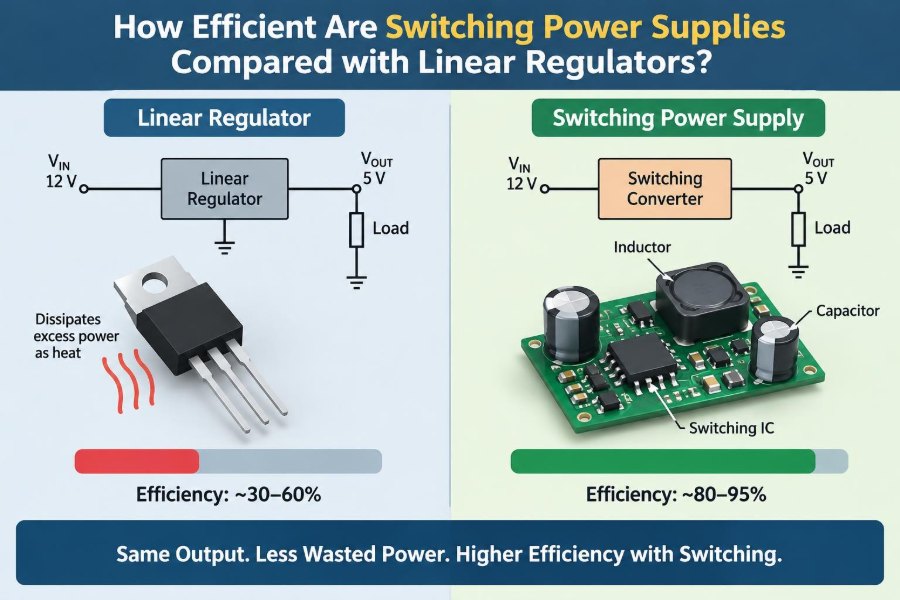
A linear regulator commonly operates with an efficiency close to the ratio of output voltage to input voltage when its own quiescent current is small. A 5 V linear regulator fed from 12 V can therefore be only about 42% efficient at a given load: most of the remaining input power becomes heat.
A well-designed switching converter often reaches efficiencies in the high tens of percent and can exceed 90% in favorable conditions. Its losses are real, but it transfers energy through inductors, capacitors, switches, and control circuitry rather than deliberately dropping excess voltage across a pass element.
High efficiency is not an automatic reason to use a switcher. At low current, or where electrical noise and design simplicity dominate, a linear regulator may still be the more effective system choice.
🔋 What a Power Regulator Actually Does
A regulator maintains an intended output voltage as input voltage, load current, and temperature change. Without regulation, a circuit powered from a battery or unregulated adapter may see a voltage that changes enough to cause resets, inaccurate measurements, or component damage.
The regulator takes input power, delivers output power, and consumes or loses the rest. The basic relationship is:
Efficiency = output power / input power × 100%Output power is approximately output voltage multiplied by output current. The gap between input and output power is dissipated as heat, stored temporarily in reactive components, or consumed by the regulator’s control circuitry.
📏 The Core Linear-Regulator Efficiency Rule
In a conventional linear regulator, input current is nearly the same as load current. The device controls its output by behaving like a variable resistance in series with the load, dropping whatever voltage is not needed at the output.
Ignoring quiescent current, the useful approximation is:
η ≈ Vout / VinFor a 3.3 V rail generated from 5 V, the theoretical maximum is about 66%. From 12 V to 3.3 V, it falls to about 28%. The lost voltage is not mysterious: it appears across the regulator and produces heat in proportion to current.
🔥 Why Linear Regulators Get Hot
Linear-regulator dissipation is easy to calculate:
Ploss ≈ (Vin − Vout) × IoutConsider a hypothetical circuit drawing 500 mA at 5 V from a 12 V source. The output consumes 2.5 W, while the regulator dissipates roughly 3.5 W. A small package may rapidly exceed a safe junction temperature without a large copper area or heatsink.
This thermal behavior is often the first practical limit. Even when a linear regulator is electrically rated for the current, it may not be able to dissipate the associated heat in the actual enclosure.
🧊 Why Switching Converters Waste Less Power
A switching converter rapidly turns a transistor fully on and off. When the switch is on, its voltage drop can be low; when it is off, its current is low. Ideally, voltage and current do not remain high at the same time, so little power is dissipated in the switching device.
An inductor, transformer, capacitor, or combination of these components stores and releases energy between switching intervals. Feedback adjusts the switching duty cycle, frequency, or peak current so the output remains regulated.
Real switches have resistance, transitions are not instantaneous, magnetic components have losses, and control circuits consume energy. Still, this method avoids the continuous, intentional voltage drop that defines a linear regulator.
🔄 Buck Converters Step Voltage Down
A buck converter reduces a higher input voltage to a lower output voltage. It is the common topology behind point-of-load converters, USB-powered boards, automotive electronics, and many consumer adapters.
During an on interval, energy flows into the inductor and load. During an off interval, the inductor keeps current flowing through a diode or synchronous transistor. The output capacitor smooths the resulting ripple.
For a 12 V-to-5 V, 1 A rail, a buck converter can dramatically reduce heat compared with a linear regulator. The advantage grows as the input-to-output voltage gap and output current increase.
⬆️ Boost Converters Step Voltage Up
A boost converter produces an output voltage higher than its input. Linear regulators cannot perform this function because they can only drop voltage; they cannot create a higher regulated rail from a lower source.
Boost converters are used when a single lithium-ion cell must power a 5 V USB device, when a battery voltage falls below a required rail, or when LEDs need a higher series-string voltage. Their efficiency depends strongly on conversion ratio because higher output voltage requires higher input current.
The ability to step up voltage is therefore not merely an efficiency benefit. It is a functional capability that makes many battery-powered products possible.
🔁 Buck-Boost Converters Handle Changing Inputs
A buck-boost converter can regulate when the input is sometimes above and sometimes below the desired output. This is valuable for batteries whose voltage changes substantially during discharge and for automotive systems with cranking dips or surge conditions.
Several circuit families fit this description, including inverting buck-boost, non-inverting four-switch buck-boost, SEPIC, and flyback-derived arrangements. They differ in polarity, complexity, efficiency, and isolation options.
Because energy may pass through more switches or magnetic paths than in a simple buck, buck-boost designs can be less efficient than an equivalent buck operating under easy conditions. They remain preferable when the input range demands their flexibility.
🧮 Comparing a Practical Example
Suppose a digital subsystem needs 3.3 V at 1 A from a 12 V source. The load needs 3.3 W. A linear regulator would dissipate approximately 8.7 W, which is generally an impractical thermal burden for a compact board.
If a switching converter delivered 3.3 W at 90% efficiency, its input power would be about 3.67 W and its loss about 0.37 W. Actual performance varies with components, frequency, airflow, and layout, but the scale of the difference is clear.
| Approach | Approximate input power | Approximate heat loss | Design consequence |
|---|---|---|---|
| 12 V to 3.3 V linear, 1 A load | 12 W | 8.7 W | Major thermal management required |
| 12 V to 3.3 V switcher, assumed 90% | 3.67 W | 0.37 W | Much easier thermal design |
These figures are illustrative calculations, not a claim that every switching module will achieve 90% in every application.
📉 Where Switching Losses Come From
Switching converters do not eliminate loss; they distribute it among several mechanisms. Understanding those mechanisms helps explain why a datasheet efficiency curve is more useful than a single headline number.
- Conduction loss: resistance in MOSFETs, inductor windings, traces, and capacitors produces I²R heating.
- Switching loss: voltage and current overlap briefly while transistors turn on and off.
- Magnetic loss: inductor core and winding losses increase with current, frequency, and ripple.
- Gate-drive and control loss: the controller must charge transistor gates and operate its internal circuitry.
- Rectifier loss: diode forward drop can be substantial, especially at lower output voltages.
Good converter design is largely the art of balancing these losses across the expected operating range.
🧠 Synchronous Rectification Improves Efficiency
Older or simpler buck converters often use a diode as the freewheeling path. A diode loses power equal to its forward voltage times current, which can be significant in a low-voltage, high-current rail.
Synchronous converters replace that diode with a controlled MOSFET. Its loss is mainly based on on-resistance, so it can be much lower than diode loss when properly driven.
The gain is especially useful for outputs such as 1.0 V, 1.8 V, or 3.3 V. However, synchronous control adds complexity and must prevent both switches from conducting simultaneously, a fault called shoot-through.
📊 Efficiency Changes with Load Current
No regulator has one universal efficiency value. A switching supply may be very efficient near a moderate or high load but less efficient at light load because fixed control and gate-drive losses become a large share of the output power.
Some controllers enter pulse-skipping, burst, or pulse-frequency-modulation modes at light load. These modes can improve battery life, but they may change ripple frequency and complicate noise-sensitive measurements.
Linear-regulator efficiency by voltage ratio changes less with load in the ideal model, yet quiescent current becomes increasingly important as load current becomes very small.
🌙 Quiescent Current Matters in Sleep Mode
Quiescent current is the current a regulator consumes to remain active, even when the load is tiny. For a device that sleeps most of the time, this value can dominate battery life more than full-load efficiency.
A low-quiescent-current linear regulator can be excellent for an always-on sensor drawing microamps. A larger switch-mode controller might waste more energy simply operating its control circuit than the sensor consumes.
Always inspect the operating mode behind a quiescent-current specification. Some values apply only with no switching, disabled features, or a particular input voltage.
🎯 Dropout Voltage Defines a Linear Regulator’s Limit
A linear regulator needs input voltage above its output voltage by some margin to regulate. This margin is called dropout voltage. Low-dropout regulators, usually called LDOs, reduce that required margin and are useful when input and output are close.
A 3.3 V LDO fed from a nearly discharged 3.7 V nominal lithium-ion cell may be practical if its dropout is low enough at the required current. A traditional linear regulator with a larger dropout may stop regulating much earlier.
Low dropout does not overturn the efficiency rule. It improves usable battery range and reduces loss when voltage headroom is small.
📦 Size Is More Than the Regulator IC
A linear supply can require only an IC and a few capacitors. A switching supply typically needs an inductor or transformer, additional capacitors, feedback parts, and careful physical placement.
At low power, this extra circuitry may occupy more board area than an LDO solution. At higher power, the switcher’s smaller heatsink requirement can reverse the comparison, making the total system smaller.
Frequency also affects size. Higher switching frequency can permit a smaller inductor and capacitors, but it usually increases switching losses and can make electromagnetic interference harder to manage.
📡 Switching Noise and EMI
Switching edges contain high-frequency energy. Fast changes in current create voltage disturbances through stray inductance, while fast voltage changes couple capacitively into nearby circuits. These effects create conducted and radiated electromagnetic interference, usually shortened to EMI.
A linear regulator is not noiseless, but it generally does not create the same high-frequency switching waveform. That makes it attractive for sensitive analog stages, low-noise references, radio-frequency circuits, and precision data-converter supplies.
Noise is manageable, not unavoidable. Proper layout, input and output filtering, shielding where justified, controlled switching-edge rates, and thoughtful grounding can produce very clean switch-mode rails.
🗺️ PCB Layout Can Decide the Outcome
A switching regulator copied from a schematic but laid out poorly may run hot, emit noise, ring excessively, or regulate unstably. The most critical current loops must be physically small and use short, wide connections.
In a buck converter, the loop involving the input capacitor, high-side switch, low-side switch or diode, and their return path carries sharp pulsed current. Place the input capacitor close to the switching devices, not at the far end of a long trace.
Keep the feedback node away from the switch node and inductor. A quiet ground reference and the manufacturer’s layout guidance are often as important as selecting the converter IC itself.
🌊 Output Ripple Is Not the Same as Regulation
A supply can have an accurately regulated average output voltage while still carrying ripple and switching spikes. Ripple is the periodic voltage variation caused by inductor current, capacitor impedance, control behavior, and parasitic effects.
Output capacitors help, but capacitance alone is not the whole answer. Equivalent series resistance and inductance affect how a capacitor responds at switching frequencies and during fast load changes.
When evaluating a rail, ask what the load actually tolerates: average voltage error, peak-to-peak ripple, broadband noise, and transient deviation are different specifications.
⏱️ Load Transients Test Control Performance
Digital circuits can change current demand rapidly when processors wake, radios transmit, or motors start. A regulator must respond before the output voltage moves outside the load’s acceptable range.
Linear regulators can offer simple, low-noise transient behavior, although their response still depends on control-loop design and output capacitor requirements. Switchers may respond very quickly too, but their compensation network and energy-storage components require careful design.
Do not choose solely from steady-state efficiency. A converter that is efficient but permits excessive voltage droop during a radio burst is not suitable for that load.
🛠️ The Linear Regulator’s Real Advantages
Linear regulators remain widely used because they solve many problems cleanly. They are often inexpensive, easy to understand, and quick to implement when dissipation is modest.
- Very low output noise is achievable with suitable devices and capacitors.
- Minimal external parts simplify prototypes and low-volume designs.
- There is no inductor-generated magnetic field or switching node.
- They work well when input voltage is only slightly above output voltage.
- Some ultra-low-power LDOs have exceptionally low quiescent current.
For a 5 V source feeding a quiet 4.5 V analog rail at a small current, an LDO can be a rational and elegant choice.
🏗️ The Switcher’s Real Advantages
Switching supplies excel where power conversion is substantial. They reduce battery drain, lower heat generation, and allow voltage step-down, step-up, inversion, or isolation depending on topology.
Their efficiency can remove the need for large heatsinks and enable sealed products that would otherwise overheat. In portable equipment, less wasted power often directly translates to longer operating time or a smaller battery.
They also support high-current low-voltage loads that would be thermally unrealistic with a linear pass device. Modern processors, FPGA cores, and LED systems depend heavily on this capability.
🔗 Cascading a Switcher and an LDO
A common compromise is to use a switching regulator for the large voltage conversion, then an LDO to clean up a noise-sensitive rail. For example, a 12 V input may first become 3.8 V through a buck converter, followed by a 3.3 V LDO for an analog section.
This arrangement limits the LDO’s voltage drop while taking advantage of its noise filtering and simple local regulation. It is not automatically quiet: switching noise can still bypass the LDO through parasitic paths or exceed its rejection capability at high frequencies.
Check the LDO’s power-supply rejection ratio across frequency, not merely its low-frequency value. Also budget the LDO’s heat at worst-case input voltage and load current.
🚗 Input Conditions Change the Best Choice
The nominal source voltage is rarely the complete story. A “12 V” vehicle system, for example, can experience wide variations, transients, reverse-battery hazards, and cranking events. A battery pack may have a high voltage when fully charged and a much lower voltage near depletion.
Choose components using worst-case input voltage, not only a label on the adapter or battery. Verify absolute maximum ratings, protection requirements, and the regulator’s operating range.
An efficient converter that survives only the normal voltage is not a robust power solution.
🌡️ Thermal Design Is a System Calculation
Temperature affects reliability, efficiency, and available output current. Semiconductor junction temperature depends on power loss, package thermal resistance, copper area, airflow, enclosure design, and nearby heat sources.
For linear regulators, calculate dissipation over the highest input voltage and expected load. For switchers, include losses in the controller, inductor, diode or synchronous MOSFETs, and input/output capacitors.
Thermal shutdown is a protection feature, not a normal operating strategy. A regulator that repeatedly enters shutdown may cause intermittent system behavior while remaining dangerously hot.
🧪 Measure Efficiency Correctly
Measure input voltage and current at the regulator input, then output voltage and current at the load or a clearly defined output point. Calculate both powers using readings taken under the same stable condition.
At higher ripple or non-sinusoidal current, instrument bandwidth and measurement method matter. A basic multimeter may not capture fast waveform details, while a scope probe with a long ground lead can exaggerate switching spikes.
Use short probe-ground connections, appropriate bandwidth limits, and a representative load. Then test across input voltage and load-current ranges rather than reporting one convenient operating point.
⚠️ Common Selection Mistakes
Several errors recur in power designs because a regulator’s advertised current rating or peak efficiency looks more decisive than it really is.
- Selecting an LDO by current rating without calculating heat dissipation.
- Assuming a switcher’s maximum efficiency applies at every load and input voltage.
- Ignoring inductor saturation current and temperature rise.
- Using capacitor values without checking voltage rating, bias derating, ESR, and stability requirements.
- Routing sensitive feedback traces beside a noisy switch node.
- Forgetting startup current, short-circuit behavior, and output discharge needs.
Datasheets provide essential limits, but application notes and reference layouts often reveal the practical conditions behind those limits.
🧭 A Practical Selection Method
Start with the source: its minimum and maximum voltage, impedance, surge behavior, and energy capacity. Then define the load: voltage tolerance, normal and peak current, noise sensitivity, startup demand, and sleep current.
- Calculate linear-regulator loss at worst-case input voltage and load.
- Decide whether that heat is acceptable in the actual package and enclosure.
- If not, select a suitable switching topology based on required step-down, step-up, or buck-boost operation.
- Review efficiency curves at realistic input voltage and load points.
- Design layout, filtering, protection, and thermal paths as part of the converter—not as later additions.
- Prototype and test ripple, EMI behavior, temperature, and load transients.
This approach avoids treating efficiency as a single component specification detached from the rest of the product.
🧩 When a Linear Regulator Is the Better Answer
Choose a linear regulator when the voltage drop is small, the current is low, dissipation is safely manageable, and low noise or design simplicity has high value. A post-regulator after a switcher is another strong use case.
For instance, dropping 3.6 V to 3.3 V at a modest current creates comparatively little heat. An LDO may be smaller, quieter, and easier to validate than a switching solution.
The key question is not whether a switcher is more efficient in theory. It is whether the energy saved is meaningful for the thermal, battery, size, and cost constraints of the actual design.
🚀 When a Switching Supply Is Clearly Better
Choose a switching converter when there is a large input-to-output voltage difference, substantial load current, battery runtime pressure, or a need to step voltage up or down across a wide input range.
A 24 V industrial input feeding 5 V electronics, a 12 V battery powering a 3.3 V processor rail, and a single-cell product requiring regulated 5 V are all strong switch-mode candidates. The avoided heat is typically too large to ignore.
Invest in layout, component selection, and verification early. The efficiency advantage is realized only when the converter is electrically stable, thermally sound, and compatible with the surrounding system.
✅ The Core Takeaway: Manage Energy, Not Just Voltage
Linear regulators control voltage by dissipating the unwanted difference, so their efficiency is fundamentally constrained by the input-to-output voltage ratio. Switching power supplies convert energy in timed packets through magnetic and capacitive storage, allowing far less waste in many applications.
That difference makes switchers the default choice for significant voltage conversion and power delivery. Yet linear regulators retain a vital role where headroom is small, currents are low, noise must be minimal, or straightforward implementation outweighs saved power.
The best regulator is the one that meets voltage, current, noise, thermal, battery-life, size, and reliability requirements together—not the one with the highest efficiency number alone.
Choose the topology from the complete operating condition, then validate it on real hardware. Power design becomes much clearer once every “lost” watt is treated as a physical design problem with a destination: usually heat, and occasionally a better conversion strategy. 🔌🌡️⚙️