
A phone charges faster from one adapter than another. A motor seems more forceful when its supply voltage is raised. A laboratory power supply has a tempting voltage knob, and turning it clockwise can feel like asking a circuit to work harder.
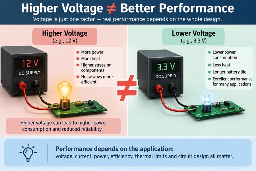
That intuition is understandable, but it is incomplete. Voltage is a difference in electric potential, not a universal performance control. Whether a higher voltage helps depends on the device, the circuit topology, the load, the timing, the thermal design, and the limits stated by the manufacturer.
In electronics, the best voltage is usually not the largest voltage available. It is the voltage that lets every part of a system operate within its intended electrical, thermal, and reliability limits.
Understanding that distinction prevents damaged components, misleading measurements, inefficient designs, and unsafe experiments. It also explains why a modern processor may operate near one volt while an electric vehicle traction system uses hundreds of volts.
⚡ Voltage Is Electrical Potential Difference
Voltage describes the energy available per unit charge between two points. It is measured in volts, and it tells us how strongly an electric field can push charge through a circuit.
A useful analogy is water pressure. More pressure can encourage more flow through a pipe, but flow still depends on the pipe’s restriction, valves, and whether the plumbing can tolerate that pressure. Voltage similarly interacts with resistance, impedance, switching behavior, and circuit design.
Voltage alone does not state how much energy a source can deliver, how much current will flow, or whether a load will work correctly.
🔋 Performance Has More Than One Meaning
When someone says a device performs better, they may mean it produces more output power, runs faster, has less noise, uses less energy, communicates more reliably, or lasts longer. These goals can conflict.
For example, raising a microcontroller clock speed may improve computation throughput, but it can increase supply current and heat. Raising the supply voltage can sometimes support that speed, yet it may shorten battery life and reduce long-term reliability.
Always define the performance metric before deciding whether a voltage change is useful.
📐 Ohm’s Law Explains Only Part of the Story
For an ideal resistor, Ohm’s law states that current equals voltage divided by resistance: I = V/R. If resistance remains fixed, increasing voltage increases current.
That rule is valuable, but many real electronic loads are not fixed resistors. LEDs, motors, batteries, integrated circuits, switching converters, and radio circuits all change behavior as voltage, temperature, frequency, or operating mode changes.
Applying resistor logic to every circuit is a common source of incorrect predictions.
🔥 Power Rises Faster Than Voltage
Electrical power is the rate of energy transfer: P = V × I. For a resistor with fixed resistance, this can also be written as P = V²/R.
The squared relationship matters. If the voltage across a fixed resistor doubles, its power dissipation becomes four times larger. A resistor that was merely warm can become dangerously hot, even though the voltage change seemed modest.
Component power ratings, copper trace capacity, enclosure temperature, and cooling all become part of the voltage decision.
🧱 Every Component Has Absolute Limits
Datasheets commonly list recommended operating conditions and absolute maximum ratings. These are not interchangeable. Recommended conditions describe the range in which expected operation is specified; absolute maximum ratings describe boundaries that should not be exceeded, even briefly in many cases.
A capacitor can have a voltage rating, a transistor can have a maximum drain-source voltage, and an integrated circuit can have a maximum supply voltage. Exceeding such limits may cause immediate failure, gradual degradation, or operation that appears normal until later.
A higher rating on one part does not make the whole circuit safe at that voltage.
🧠 Digital Logic Needs Defined Voltage Ranges
Digital circuits treat voltage as logic states only within specified ranges. A logic input has thresholds for recognizing a low or high level, while the power supply establishes the operating conditions for its internal transistors.
Supplying a 3.3 V microcontroller with 5 V because “more voltage gives a stronger signal” can damage its internal gates. Conversely, operating it below its required supply range may lead to reset loops, memory errors, or unreliable peripheral behavior.
Digital performance is therefore about valid margins, timing, and supply integrity—not simply a taller voltage level.
⏱️ Higher Supply Voltage Can Change Switching Speed
In some digital technologies, a higher supply voltage can make transistors switch more quickly. It gives circuits more drive strength and may help meet timing requirements at a higher clock frequency.
That benefit has a price. Dynamic switching power is approximately related to capacitance, frequency, and the square of supply voltage: P ≈ C × V² × f. Leakage current can also change with voltage and temperature.
This is why processors use carefully managed voltage-frequency operating points rather than simply running at the highest supply voltage possible.
🌡️ Heat Is Often the First Practical Limit
Extra electrical power that does not become useful output usually becomes heat. Junction temperature rises inside semiconductors, and heat must travel through packages, circuit boards, heat sinks, and surrounding air.
High temperature can alter component parameters, reduce battery life, soften insulation, and accelerate aging mechanisms. A circuit may pass a brief bench test at elevated voltage but fail after prolonged operation in a warm enclosure.
Thermal design is not an afterthought; it is part of electrical performance.
🧯 Voltage Margin Is Not Permission to Overdrive
Designers often include margin between normal operation and a component’s maximum limit. That margin accounts for supply tolerance, ripple, startup overshoot, temperature, manufacturing variation, and transients.
Using the margin as an everyday operating range removes the protection it was meant to provide. A nominal 12 V rail, for instance, can momentarily exceed 12 V because of cable inductance, load changes, or regulator behavior.
Good design leaves room for real-world variation rather than treating a maximum number as a target.
💡 LEDs Need Current Control, Not Just More Voltage
An LED has a forward voltage, but it is not a voltage-regulating component. A small rise in applied voltage beyond the operating region can produce a large current increase because the LED’s current-voltage curve is steep.
Without a series resistor or constant-current driver, increasing voltage can quickly overheat and destroy the LED. The brightness may increase briefly, which makes this mistake seem successful at first.
For LED systems, current sets light output more directly, while voltage must be high enough for the LED string and driver to operate correctly.
🌀 Motors Respond Differently Under Load
For a basic DC motor, raising voltage generally raises no-load speed. It can also increase available current and torque during startup or heavy loading, provided the driver and winding can handle it.
But a motor is an electromechanical system. Higher voltage can increase winding heating, brush wear in brushed motors, bearing stress at excessive speed, and mechanical risk for attached gears or fans.
A motor rated for a particular voltage and duty cycle should be paired with a controller that limits current and handles the expected load.
🔌 Power Delivery Depends on Current Too
Two supplies can have the same voltage and very different capabilities. A 12 V supply rated for a small current may collapse when asked to run a high-power motor, while another 12 V supply remains stable.
Power availability depends on both voltage and current capacity. Internal resistance, current limiting, cable resistance, connector ratings, and protection circuits determine what the load actually receives.
A higher-voltage supply with poor regulation or inadequate current capacity is not automatically an upgrade.
📉 Voltage Drop Can Defeat a Good Supply
Cables, connectors, switches, and printed-circuit-board traces have resistance. When current flows, they develop a voltage drop described approximately by Vdrop = I × R.
A device may see much less than the supply’s measured voltage if it is connected through long, thin wires. This is especially noticeable with motors, heaters, and radio transmitters that draw short bursts of current.
Measuring voltage at the load while it operates is more informative than measuring only at the power supply terminals.
🔄 Switching Regulators Change the Trade-Off
A buck converter steps voltage down, a boost converter steps it up, and a buck-boost converter can do both. These circuits exchange voltage and current while losing some energy to switching and conduction losses.
For a given power level, a higher distribution voltage can reduce current and therefore reduce resistive cable loss. That is one legitimate reason higher voltages are used in some systems.
It does not mean every load should receive that higher voltage directly. The converter exists to deliver the voltage the load actually needs.
🏠 Why USB Power Systems Evolved
Charging systems provide a familiar example of negotiated voltage. Delivering more power through a cable can be achieved by increasing current, increasing voltage, or both within the system’s rules.
Modern charging arrangements may use higher voltage only after compatible equipment communicates and agrees on an appropriate mode. The receiving device then uses internal power-management circuitry to charge its battery safely.
Connecting an arbitrary higher-voltage source to a low-voltage device bypasses that coordination and can cause immediate damage.
🔊 Analog Circuits May Benefit from Headroom
In analog amplifiers, supply voltage can affect signal headroom: the maximum signal swing available before clipping or distortion occurs. A higher supply can be useful when an amplifier is designed for it and needs to drive a larger output signal.
However, noise, distortion, bandwidth, bias current, and thermal drift also matter. An amplifier powered from a higher rail is not automatically quieter or more accurate.
The input and output requirements, load impedance, and device specifications determine whether extra headroom produces a meaningful improvement.
📻 RF Circuits Can Become Less Predictable
Radio-frequency circuits are sensitive to bias conditions, layout, impedance matching, parasitic capacitance, and component tolerances. Raising a supply voltage can alter gain, output power, linearity, or current draw.
Past a suitable operating point, a transistor stage may generate more distortion, radiate unwanted emissions, or become thermally unstable. The desired result is a controlled signal, not maximum transistor stress.
RF work relies on measurement and characterization; intuition based on DC circuits is rarely enough.
🧪 Measurement Equipment Has Its Own Limits
Oscilloscope probes, multimeter inputs, current shunts, electronic loads, and differential probes all have voltage, current, frequency, and energy limits. Connecting the wrong instrument can be hazardous and can invalidate a measurement.
Ground-referenced oscilloscope probes deserve special care. On many bench oscilloscopes, the probe ground is connected to protective earth. Clipping it to the wrong point can create an unintended short circuit.
Before testing a higher-voltage circuit, verify the instrument ratings and the measurement method—not just the circuit’s expected voltage.
🛡️ Higher Voltage Raises Safety Requirements
The hazard of an electrical system depends on available energy, current path, environment, insulation, exposed conductors, stored charge, and fault conditions. Voltage is a major factor, but it is not the only one.
Higher voltages require stronger insulation, adequate clearances and creepage distances, appropriate connectors, guarded terminals, and safe discharge methods for capacitors. Requirements vary by application and jurisdiction.
Do not extrapolate low-voltage hobby practices to mains-powered or high-energy systems. When safety requirements are uncertain, use qualified supervision and applicable standards.
⚡ Transients Can Exceed the Nominal Voltage
A nominal supply label does not describe every moment in a circuit. Inductive loads such as relays, solenoids, and motors can generate voltage spikes when current is interrupted. Cable inductance and fast switching can create ringing as well.
These short events can exceed a semiconductor’s limit even when a multimeter reports a safe average value. Flyback diodes, transient suppressors, snubber networks, careful layout, and suitable switching devices are common protective measures.
Design for the worst credible transient, not only the steady-state supply value.
🔋 Batteries Do Not Hold One Exact Voltage
A battery’s terminal voltage changes with state of charge, load current, temperature, chemistry, and age. A “nominal” battery voltage is a useful label, not a guarantee of a fixed output.
A circuit connected directly to a battery must tolerate the full expected voltage range, including charging conditions where applicable. It must also manage low-voltage operation so that behavior remains predictable as the battery discharges.
Battery-powered designs often need regulation because the load needs a steadier voltage than the battery naturally provides.
🧩 Interfaces Fail When Voltage Domains Clash
Mixed-voltage systems are common: a 1.8 V sensor may communicate with a 3.3 V controller, which connects to a 5 V peripheral. Directly joining signals without checking input thresholds and maximum ratings can damage the lower-voltage device.
Level shifters, resistor dividers, open-drain interfaces, buffers, and properly chosen logic families solve different versions of this problem. The right method depends on direction, speed, protocol, and whether signals need bidirectional operation.
“The signal is only digital” is not a safe reason to ignore voltage compatibility.
🧾 Read Datasheets in the Right Order
A practical datasheet review begins with the recommended supply range, then absolute maximum ratings, electrical characteristics, typical application circuit, thermal information, and layout guidance.
Look for conditions attached to each specification. A current limit, output swing, switching frequency, or accuracy figure may apply only at a particular supply voltage, temperature, or load.
Datasheets do not merely identify a maximum voltage. They explain the conditions under which the component delivers the performance you want.
🧰 A Practical Voltage-Selection Workflow
Choose voltage as a system decision rather than an isolated number. Start with what the load needs, then work outward through the power source, distribution path, protection, and environment.
- Define the required output: speed, torque, light, signal swing, computing rate, or another measurable target.
- Identify the load’s normal range, peak current, startup behavior, and maximum ratings.
- Account for source variation, cable drop, ripple, and switching transients.
- Calculate likely dissipation in components, traces, and connectors.
- Check thermal conditions at the real duty cycle and ambient temperature.
- Add regulation, current limiting, monitoring, and protection where the risk warrants them.
🚫 Common Mistakes When Chasing More Voltage
One frequent mistake is using a supply with the same connector but a different voltage. Connector fit says nothing about electrical compatibility.
- Assuming a larger adapter can “force” excess power into a device.
- Using absolute maximum ratings as normal operating targets.
- Ignoring startup and stall current in motors.
- Driving LEDs from voltage without current limiting.
- Measuring only steady-state voltage while ignoring spikes.
- Increasing a supply before checking the regulator, capacitor, and input ratings of every connected module.
Most of these errors are avoidable with a datasheet, a meter, and a deliberate pre-power checklist.
🧯 Protection Circuits Add Controlled Limits
Fuses, resettable protectors, current-limit circuits, thermal shutdown, reverse-polarity protection, under-voltage lockout, over-voltage protection, and transient suppression each address different fault conditions.
Protection does not make an unsuitable voltage suitable. A fuse may not react quickly enough to save a sensitive integrated circuit, and thermal shutdown may only protect one device while another overheats first.
The most reliable approach combines correct nominal voltage with protection against credible abnormal events.
⚖️ When Higher Voltage Really Is Advantageous
Higher voltage is often useful when transmitting a fixed amount of power over distance. Because current can be lower, resistive loss in cables is reduced. It can also provide needed headroom in an appropriately designed analog circuit or enable a motor system to meet a specified speed range.
These benefits appear only when insulation, switching devices, capacitors, connectors, layout, control electronics, and safety provisions are designed for the voltage. The gain comes from a considered trade-off, not from voltage itself being inherently better.
🧭 The Core Principle: Match Voltage to the System
Voltage is one design variable among many. Current capacity determines whether the source can sustain a load, power determines energy transfer and heating, impedance shapes behavior, and thermal limits determine whether operation can continue safely.
The right question is not “Can I use a higher voltage?” It is “What voltage lets this complete system meet its required performance with acceptable heat, reliability, cost, and safety?”
Better electronic performance comes from matching voltage to the device and design constraints—not from maximizing voltage.
Once voltage is treated as a carefully chosen operating condition rather than a universal upgrade, circuit decisions become clearer, measurements become more meaningful, and hardware is far less likely to fail for preventable reasons. 🔌⚙️🛡️