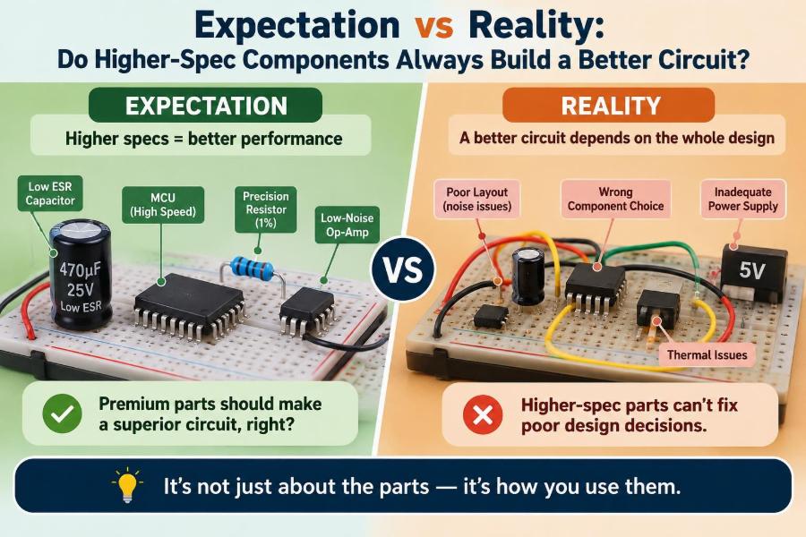

A prototype is misbehaving, so the obvious response is to upgrade the parts. Replace the 1 A regulator with a 5 A model. Choose the fastest op-amp in the catalogue. Fit a capacitor with a much higher voltage rating. Buy the lowest-resistance MOSFET available.
Sometimes that works. Often, it does not. The upgraded board may oscillate, start slowly, lose measurement accuracy, radiate more noise, or simply cost more without delivering a visible improvement.
The reason is simple but easy to overlook: a component specification describes performance under particular conditions. A circuit succeeds when its components, layout, loads, control loops, environment, and manufacturing limits work together.
Higher specification is not the same as better engineering. The better part is the one whose relevant characteristics fit the actual job with adequate margin and manageable trade-offs.
🧭 Start With the Requirement, Not the Catalogue
A specification only has meaning relative to a requirement. “Higher voltage,” “faster,” and “more accurate” sound desirable, but each must be connected to a real circuit need.
For a 3.3 V logic rail drawing 200 mA, a regulator rated for 10 A is not automatically superior to a 500 mA part. The key questions are startup behavior, heat dissipation, output noise, stability with the chosen capacitors, quiescent current, cost, and physical size.
Good component selection starts with an operating envelope: expected voltage, current, frequency, temperature, load type, accuracy target, lifetime, and fault conditions. Only then can “enough” be distinguished from “excess.”
📄 Read a Datasheet as a Set of Conditions
A headline rating is rarely a universal promise. Maximum drain current, for example, may be stated with a specified case temperature, a large heat sink, short pulses, or a package limit that is hard to achieve on a small PCB.
Datasheet graphs, test circuits, notes, and electrical-characteristics tables reveal the conditions behind the number. A 1% resistor may be 1% at room temperature, yet drift with temperature, humidity, voltage stress, or aging.
The maximum rating table defines survival limits, not normal design targets. Design recommendations and guaranteed operating conditions are usually more useful for deciding whether a part fits.
🎯 Understand Which “Better” Metric Matters
Components have multiple performance dimensions, and improving one can worsen another. A lower-resistance MOSFET may have higher gate charge. A very low-noise amplifier may consume more current. A precision reference may require more headroom or longer settling time.
Before comparing parts, identify the dominant error, loss, or risk in the system. A 0.1% resistor adds little value in a sensor circuit whose sensor itself varies by several percent across temperature.
| Component | Tempting higher spec | Possible trade-off |
|---|---|---|
| Capacitor | Higher capacitance | Higher inrush current, larger size, control-loop instability |
| Op-amp | Higher bandwidth | Oscillation risk, higher noise at some frequencies, greater supply current |
| MOSFET | Lower on-resistance | Higher gate charge and slower switching with the same driver |
| Regulator | Higher current rating | Different stability requirements, larger quiescent current, higher cost |
| Resistor | Tighter tolerance | Temperature coefficient or long-term drift may still dominate |
⚖️ Maximum Ratings Are Not Design Margins
Operating a component below its absolute maximum ratings is necessary, but it is only the first step. A robust design also allows margin for supply variation, manufacturing spread, transients, temperature, and aging.
Consider a 25 V-rated capacitor on a nominal 24 V rail. It may appear acceptable on a schematic, yet a supply tolerance or switching transient can leave almost no room. A higher voltage rating may be appropriate here—but verify its capacitance, ESR, dimensions, and behavior at the required temperature.
Margin should be deliberate rather than automatic. Excessive derating can make a design bulky or expensive; inadequate derating makes its reliability depend on unusually favorable conditions.
🌡️ Temperature Changes the Real Circuit
Most circuit behavior shifts with temperature. Semiconductor leakage rises, battery voltage changes, resistor values move according to their temperature coefficient, and capacitors can lose capacitance or gain resistance.
A part selected only from its typical room-temperature values can fail a cold startup or a hot enclosure test. The appropriate “better” component may therefore be one with a wider operating-temperature range, not one with a more impressive nominal electrical rating.
Also separate ambient temperature from junction temperature. A power device can have a safe ambient environment while its silicon junction becomes much hotter because heat cannot leave the package quickly enough.
🔥 Power Ratings Depend on Thermal Design
A resistor marked 1 W does not necessarily dissipate 1 W safely on every board. Its permitted power often falls as ambient temperature rises, and nearby heat sources can raise its body temperature further.
The same applies to regulators, LEDs, transistors, and ICs. Their thermal resistance describes the path from junction to ambient or case under particular mounting conditions. Copper area, vias, airflow, enclosure design, and board orientation all influence the result.
A physically larger component or a different package can be better than a nominally higher-rated device in the same package. Thermal performance is a system property, not a label on one part.
⚡ Faster Switching Can Create More Problems
Fast edges reduce switching loss in many power circuits, but they also contain more high-frequency energy. That energy couples through parasitic inductance and capacitance, creating ringing, electromagnetic interference, and voltage overshoot.
A faster gate driver can therefore improve efficiency while increasing stress on a MOSFET and making conducted-emissions testing harder. In some designs, a gate resistor, snubber, controlled slew rate, or slower device produces a cleaner and more reliable result.
This is not an argument against speed. It is a reminder that switching speed must be matched to the layout, voltage, current, and EMI requirements.
📐 Parasitics Become Important Before You Expect
Real components and PCB traces are not ideal. A trace has resistance and inductance; a capacitor has equivalent series resistance and inductance; adjacent conductors have capacitance. These unwanted but unavoidable properties are called parasitics.
At DC, a larger capacitor may simply store more charge. At high frequency, its package and placement can prevent it from supplying a fast current pulse effectively. A small ceramic capacitor placed close to an IC power pin may outperform a larger capacitor located several centimeters away.
At higher frequencies, physical geometry is part of the circuit. A specification upgrade cannot compensate for an unsuitable current-return path or poor placement.
🧲 Capacitor Value Is Only One Characteristic
Choosing “the biggest capacitor” is a common shortcut. Yet capacitance is only one parameter. Voltage coefficient, dielectric type, ESR, ripple-current rating, leakage, tolerance, and frequency response may matter just as much.
For instance, many ceramic capacitors with high-permittivity dielectrics lose effective capacitance under DC bias. A part marked 10 µF may provide substantially less in a high-voltage application than its label suggests. Its datasheet curves, rather than its printed value, guide the decision.
In a timing circuit, a stable dielectric may matter more than a large nominal capacitance. In a power input, ripple-current capability and ESR may be central. Match the capacitor to its role.
🔄 Regulators Need a Stable Control Loop
Linear regulators and switch-mode converters regulate through feedback loops. Their stability depends on the output capacitor, load range, compensation design, layout, and sometimes the input source impedance.
Replacing an approved output capacitor with a much larger, much lower-ESR, or different-dielectric part can alter loop behavior. The output may oscillate even though the replacement has a higher voltage rating and more capacitance.
Use the regulator datasheet’s recommended capacitor range and ESR guidance. If a design departs from it, verify transient response and stability with measurement rather than assuming a superior-looking capacitor is harmless.
📈 Higher Bandwidth Is Not Always More Accuracy
A high-bandwidth op-amp responds to faster signals, but it also admits more high-frequency noise unless the surrounding circuit limits the bandwidth. In a slow temperature measurement, excess bandwidth can make the output noisier without improving the useful information.
Amplifier selection also involves input offset voltage, bias current, common-mode range, output swing, noise density, slew rate, gain-bandwidth product, and stability at the intended gain. No single number captures suitability.
A modest amplifier with low offset and appropriate bandwidth can outperform a faster device in a precision low-frequency system. Conversely, a slow precision amplifier may be unsuitable for a rapid control loop.
🎚️ Precision Means More Than Initial Tolerance
A tight initial tolerance tells you how close a part is to its nominal value when supplied. It does not fully predict how well that value remains controlled over temperature, time, moisture exposure, voltage, or mechanical stress.
In a voltage divider used for measurement, ratio tracking between two resistors can matter more than the absolute tolerance of either resistor. A matched resistor network may deliver more stable results than two individually precise parts from unrelated batches.
For accurate systems, build an error budget. Include reference error, resistor drift, amplifier offset, ADC behavior, sensor error, calibration method, and environmental effects. Upgrade the term that actually dominates.
🪫 Low Quiescent Current Has Its Own Costs
Quiescent current is the current an IC consumes to operate itself, excluding much of the load current. It is crucial in battery-powered equipment that sleeps for long intervals.
However, ultra-low-power regulators may have slower transient response, lower current capacity, or restrictions on output capacitors. A very low-power comparator may trade response speed for low consumption.
For an always-on remote sensor, low quiescent current may be the decisive specification. For a mains-powered industrial controller, transient performance and robustness may matter more. The duty cycle determines the right compromise.
🚪 Voltage Headroom Can Be More Valuable Than a Higher Rating
A component can be rated to withstand a voltage and still be unable to perform properly near that voltage. An op-amp’s input common-mode range may not reach either supply rail. A regulator needs dropout voltage: the difference between input and output required to maintain regulation.
Likewise, a MOSFET’s gate-source threshold is not the gate voltage needed for low resistance. Threshold is commonly measured at a very small drain current. Check the on-resistance specification at the actual gate-drive voltage.
Design from guaranteed operating curves and conditions, especially when battery discharge or supply tolerance reduces available headroom.
🧱 Package Choice Can Defeat an Electrical Upgrade
Two parts with similar silicon performance can behave very differently because of their packages. Package selection affects thermal resistance, current capability, lead inductance, creepage distance, assembly method, and inspectability.
A tiny package can reduce loop area and save board space, yet it may be difficult to hand-assemble or dissipate enough heat. A larger package may improve reliability and manufacturing yield, even if it appears less modern.
For high-current paths, inspect copper connection geometry as carefully as the component rating. A narrow trace or weak connector can become the limiting component long before the semiconductor does.
🧩 The PCB Layout Is Part of the Specification
A datasheet evaluation board often uses a carefully optimized layout. Copying only the schematic while changing component placement can produce an entirely different result.
Keep high-current switching loops compact, place decoupling capacitors close to the pins they support, provide controlled return paths, and separate sensitive analog nodes from noisy power nodes where practical. These are electrical requirements, not cosmetic layout preferences.
A premium converter IC cannot correct an excessively long feedback trace routed beside a switching node. In that situation, a layout change is more valuable than a component upgrade.
🔊 Noise Is a System Budget, Not an Op-Amp Label
Noise can originate in resistors, references, sensors, switching regulators, digital clocks, cables, and environmental pickup. Selecting a low-noise amplifier helps only if its noise is significant within the total measurement bandwidth.
For example, lowering amplifier noise may have little effect when a high-value resistor network produces most of the thermal noise. Reducing resistance may then help, but it could increase power consumption or loading of the signal source.
Define the frequency range of interest and estimate the main contributors. Filtering, grounding, shielding, layout, and sampling strategy may provide a larger improvement than an expensive active component.
🛡️ Protection Parts Must Survive the Actual Transient
A higher-voltage TVS diode is not automatically better protection. Its standoff voltage must stay above normal operating voltage, while its clamping voltage must remain low enough to protect the downstream circuit during the expected surge.
Its pulse capability, dynamic resistance, placement, trace inductance, and return path all matter. A protective device placed far from the connector can allow a fast transient to develop damaging voltage along the intervening trace.
Protection design begins by understanding plausible threats: reverse connection, inductive switching, electrostatic discharge, load dump, or external cable transients. Select and locate components for that threat model.
🔌 Connectors, Fuses, and Cables Set Hard Limits
It is easy to focus on ICs while overlooking electromechanical parts. A circuit may contain a 20 A-rated MOSFET, but a connector, crimp, cable, fuse holder, or PCB trace could be the safe current limit.
Contact resistance creates heat proportional to the square of current. A small increase in resistance from wear, contamination, or poor crimping can have a significant effect at high current.
Choose ratings for the assembled path, including derating for temperature and repeated use. A strong semiconductor does not make a weak interconnect safe.
🏭 Manufacturing Variation Changes What “Works” Means
A bench prototype often uses one set of components, one board, and favorable conditions. Production units introduce tolerance stacks: resistor values, capacitor bias effects, IC thresholds, solder variation, supply differences, and layout-dependent assembly variation.
Design margin turns a circuit that works once into a circuit likely to work repeatedly. This is particularly relevant for reset circuits, oscillator startup, current limits, and analog thresholds near decision boundaries.
When substituting components, compare every relevant parameter, not just the ordering code’s headline values. “Equivalent” parts can have different pinouts, thermal behavior, startup characteristics, or qualification status.
⏳ Reliability Is Not Maximized by Every Maximum
Operating parts with reasonable electrical and thermal margin generally reduces stress, but over-specification can introduce other reliability concerns. A much larger capacitor may stress a switch or rectifier with inrush current. A faster switching edge may create repeated voltage overshoot.
Long-term reliability also depends on technology choice. Electrolytic capacitors, ceramic capacitors, relays, connectors, and semiconductors each have different aging mechanisms and environmental sensitivities.
The goal is controlled stress across the complete operating life, not the highest number beside every symbol on the schematic.
💰 Cost Is More Than Unit Price
A high-specification part can increase bill-of-material cost, but that is only one economic effect. It may require a larger footprint, additional driver circuitry, tighter assembly controls, or a more complex test procedure.
On the other hand, a slightly more capable component can lower total cost if it simplifies protection, improves thermal margin, or reduces field failures. Cost decisions are engineering decisions when viewed across the whole product.
Ask what the upgrade eliminates or improves in the system. If the answer is only “it has a larger number,” its value has not yet been established.
📦 Availability and Lifecycle Are Performance Factors
A part that is electrically excellent but difficult to source can make a design fragile. Availability, lead times, package options, second-source compatibility, and manufacturer lifecycle information all affect whether a design can be built and maintained.
For long-lived equipment, favor components with stable supply and documented alternatives where the application permits. This may mean choosing a well-understood mainstream part over a narrowly specialized option.
Never assume a substitute is drop-in simply because it shares a package. Recheck ratings, timing, passive-component requirements, and startup behavior.
🧪 Measure the Failure Mode Before Upgrading
When a circuit fails, identify what is actually wrong. Is the regulator oscillating? Is a voltage drooping during a load step? Is a MOSFET overheating? Is a sensor reading noisy only when a motor runs?
Use appropriate instruments and probing methods. A long ground lead on an oscilloscope probe can itself exaggerate ringing measurements. Current probes, short ground springs, differential probes, thermal measurements, and controlled load tests can reveal different parts of the problem.
Replacing parts without diagnosis can hide a symptom while preserving the cause. A measurement-driven change is easier to justify, reproduce, and document.
🧰 A Practical Component-Selection Workflow
A disciplined workflow prevents headline specifications from dominating decisions. It also makes design reviews more productive because each choice has a traceable reason.
- Define normal operation, startup, shutdown, and credible fault conditions.
- Calculate expected voltage, current, power, frequency, and thermal stress with tolerances.
- Identify the few parameters that limit performance or safety.
- Read guaranteed limits, application circuits, graphs, and package data.
- Check layout, passive components, interconnects, and protection as one system.
- Prototype under realistic load, supply, and temperature conditions.
- Document approved alternates and the reasons for required margins.
This process can feel slower than picking the most impressive part. It usually saves time by preventing late redesigns.
🚫 Common “Upgrade” Mistakes
Several patterns repeatedly create avoidable trouble:
- Replacing a stable regulator capacitor with a different type without checking loop requirements.
- Selecting a MOSFET by low on-resistance while ignoring gate charge and available driver current.
- Using a high-voltage capacitor but assuming its stated capacitance remains available under DC bias.
- Choosing a fast op-amp for a slow signal path and then chasing added noise or oscillation.
- Trusting a current rating without calculating heat in the package, traces, and connectors.
- Designing to typical values while ignoring minimum and maximum guaranteed conditions.
These are not beginner-only errors. They arise whenever a single familiar metric substitutes for whole-system analysis.
✅ When Higher-Spec Parts Really Are the Right Choice
Higher specification is often justified when it directly addresses a verified requirement. Examples include a wider temperature grade for an outdoor enclosure, a higher pulse-energy rating for a protection device, lower drift in a calibration-sensitive measurement path, or a higher-voltage rating that provides necessary transient margin.
It can also be prudent where requirements are uncertain but consequences are meaningful, provided the new part does not introduce incompatible behavior. The decision should still be checked against layout, drive capability, control-loop stability, and the rest of the bill of materials.
The question is not whether to avoid premium components. It is whether their extra capability is useful in this circuit, under these conditions.
🧠 The Core Principle: Optimize the Circuit, Not the Datasheet Number
Components are chosen for roles, not for trophies. A circuit is better when it meets its electrical, thermal, safety, reliability, manufacturing, and cost requirements with clear margin.
That may require a higher-rated part in one location, a slower or lower-power part in another, additional layout attention elsewhere, and no change at all in a fourth place. The optimum comes from interactions, not isolated rankings.
The best component is the one that solves the real system problem without creating a more serious one.
Higher-specification components can strengthen a design, but only when their relevant capability matches a verified need and their trade-offs are engineered into the whole circuit. Build from requirements, validate with measurements, and let the system—not the biggest number—make the choice. 🔌📐🧪