
A battery-powered sensor works perfectly on the bench, but resets when a motor starts nearby. A small audio circuit hums after being connected to a wall adapter. A microcontroller board runs for a few minutes, then becomes unreliable for no obvious reason.
In many projects, the circuit itself is not the real problem. The power reaching it is changing, noisy, too high, or unable to supply current when the load suddenly asks for more.
A voltage regulator is the part of a power supply that turns a varying DC input into a controlled output voltage. It is a modest component, but it often determines whether an electronic system behaves predictably.
This guide builds toward a practical simple regulator circuit, explains why each component is present, and shows how to test it safely. The focus is a common linear-regulator design: an excellent foundation for low-power projects and a useful reference before moving to switch-mode supplies.
⚡ What “Stable DC Power” Actually Means
DC, or direct current, has one intended polarity: a positive rail and a return path usually called ground. Yet a supply described as “DC” is not automatically steady. Its voltage can drift with input changes, load current, temperature, or electrical noise.
A stable supply holds its output close to a target value within its specified conditions. A 5 V regulator is not expected to produce exactly 5.000 V under every circumstance; its datasheet gives an accuracy range, load range, and operating limits.
For digital electronics, stability prevents brownouts, logic errors, and unexpected resets. For analogue circuits, it also reduces unwanted hum, measurement error, and noise coupled into sensitive signals.
🔋 Why an Unregulated Source Causes Problems
Batteries discharge gradually, adapters can have poor load regulation, and rectified transformer supplies naturally rise and fall between charging peaks. A nominal 9 V source may be substantially above or below 9 V in actual operation.
Some devices tolerate this variation. LEDs with proper current limiting, for example, can be designed across a range. A 3.3 V microcontroller, however, generally needs its supply to remain inside a narrow allowed window.
Connecting an uncertain source directly to a sensitive load can cause two opposite failures: excessive voltage may damage components, while insufficient voltage can make the circuit operate unpredictably rather than simply turn off.
🧭 The Basic Job of a Linear Regulator
A linear regulator compares its output with an internal voltage reference. It adjusts an internal pass element—effectively a controlled resistance—so the output stays near the selected voltage.
Think of it as an automatic valve in a water line. If inlet pressure rises, the valve restricts flow more; if demand changes, it responds to keep downstream pressure controlled. The analogy is imperfect, but it captures the feedback action.
The excess voltage is not converted into useful output power. It is dropped across the regulator and becomes heat, which is the defining limitation of a linear design.
🧩 Choose a Straightforward First Circuit
A fixed-output three-terminal linear regulator is the simplest useful starting point. Popular families include the 78xx series for positive voltages, where the final digits commonly indicate the nominal output: 7805 for 5 V and 7812 for 12 V.
For modern low-voltage work, choose a suitable low-dropout regulator, often abbreviated LDO, rather than assuming every 5 V regulator has the same requirements. Pinouts, capacitor requirements, maximum input voltage, and current capability vary by part.
A practical example below uses a 5 V fixed regulator supplied from a 9–12 V DC source and powering a low-current load. Treat the regulator’s datasheet as the final authority for the specific component in hand.
📋 Parts for a Simple 5 V Regulated Supply
The following parts make a robust beginner circuit. Capacitor values are common starting points, not universal substitutes for the values specified by a particular regulator datasheet.
- One 5 V linear regulator, rated for the required current
- A DC input source within the regulator’s permitted input range
- One input ceramic capacitor, typically 0.1 µF
- One output ceramic capacitor, typically 0.1 µF where recommended
- One input bulk capacitor, such as 10–100 µF, when leads are long or input ripple is present
- One output bulk capacitor, often 10–100 µF when the load changes quickly
- Prototype board, wires, connector, and optionally an LED with a series resistor as a power indicator
- A multimeter and, ideally, a current-limited bench supply
Capacitors need voltage ratings above the voltage they will experience. If using polarized electrolytic capacitors, their polarity must be correct.
🗺️ Read the Regulator Pinout Before Wiring
A three-pin package looks simple, which makes it easy to become overconfident. Looking at the front of one regulator package is not a reliable way to guess another’s pin arrangement.
Many classic TO-220 78xx regulators, viewed from the marked face with leads downward, use input, ground, output. But other regulator series and package styles may use a different order. Some have an exposed metal tab electrically connected to ground or another terminal.
Check the manufacturer datasheet for the exact part number and package before applying power. A reversed input and output connection can destroy a regulator or expose the load to an unsafe voltage.
🔗 Wire the Core Circuit
The fundamental connection is short and direct:
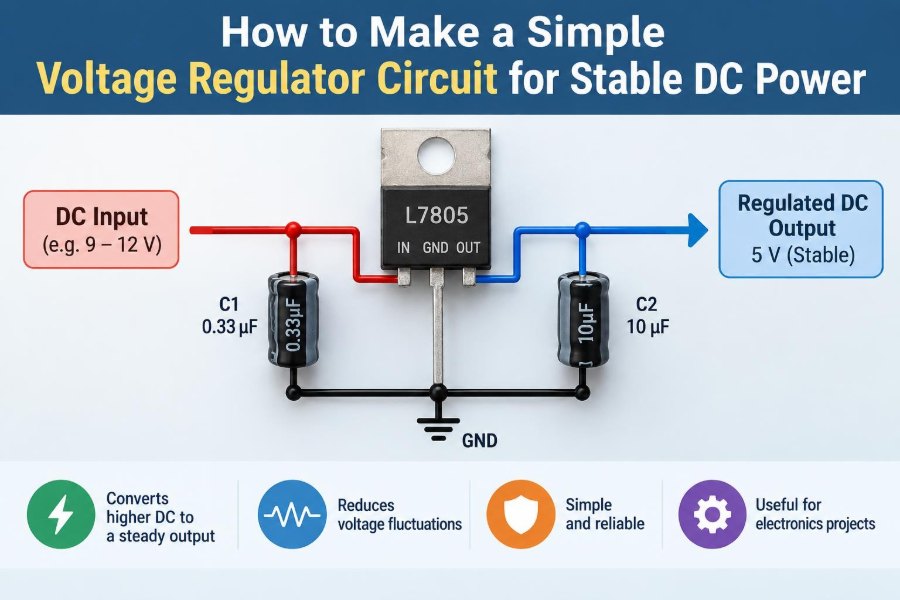
DC input +  ── input capacitor ── IN   regulator   OUT ── +5 V to load
DC input −  ───────────────────── GND             ── ground to load
                                      │
                           output capacitor from OUT to GND
Connect the positive source wire to the regulator input. Connect the source negative wire to the ground pin. Take the regulated positive output from the output pin, and connect the load return to the same ground node.
The capacitors connect across their rails: input-to-ground and output-to-ground. They are not placed in series with the power line.
🧱 Place the Input Capacitor Close to IN
The input capacitor supplies short bursts of current locally and keeps wire inductance from disturbing the regulator input. This matters even with a seemingly clean bench supply, especially when jumper wires or power leads are long.
A small ceramic capacitor is effective at high frequencies. A larger electrolytic or other bulk capacitor stores more energy for slower variations such as adapter ripple or load-related dips.
Place both as close as practical to the input and ground pins. Long leads add resistance and inductance, reducing the benefit of the capacitor precisely when fast current changes occur.
🧯 Respect the Output Capacitor Requirement
The output capacitor helps the regulator respond when the load current changes. More critically, many regulators use it as part of the control loop that keeps the device stable.
Some LDOs require a particular minimum capacitance and may specify an allowable equivalent series resistance, or ESR. A capacitor with unsuitable ESR can allow oscillation even when the measured DC output looks approximately correct on a multimeter.
Use the type, range, and placement the datasheet recommends. Do not assume that a larger capacitor automatically fixes every stability issue.
📏 Understand Input Headroom and Dropout
A regulator needs its input voltage to exceed its output voltage by some minimum amount. This difference is called the dropout voltage. If the input falls below output plus dropout, regulation is lost.
For example, a conventional 5 V regulator with roughly 2 V of needed headroom cannot maintain 5 V from a source that has fallen to 6 V. An LDO may need much less headroom, but its exact requirement changes with load current and temperature.
This is why a 9 V battery is a poor long-duration source for certain 5 V regulator arrangements: its voltage declines during use, and the regulator eventually cannot maintain its output target.
🔢 Calculate the Regulator’s Heat Load
The key linear-regulator calculation is simple:
Power dissipated = (input voltage − output voltage) × output current
If the input is 12 V, the output is 5 V, and the load draws 0.2 A, the regulator dissipates 1.4 W. That is a meaningful amount of heat for a small package, even though the load only consumes 1 W.
The calculation reveals why output current rating alone is not enough. A regulator advertised for high current may still overheat if a large input-to-output voltage difference is dropped continuously.
🌡️ Plan for Thermal Limits
Heat must travel from the regulator’s silicon die to the surrounding air through the package, copper area, and possibly a heatsink. As the die temperature rises, many regulators reduce output current or shut down to protect themselves.
Protection features are valuable, but they are not a normal operating strategy. Repeated thermal shutdown can interrupt the load, obscure the underlying design problem, and leave nearby parts exposed to heat.
For a warm regulator, reduce the input voltage if possible, reduce current, use a heatsink according to the package guidance, or move to a switching converter. Keep heatsinks clear of objects that could short exposed metal parts.
🔌 Pick the Right Input Supply
Your input source must satisfy several constraints simultaneously: correct polarity, adequate voltage headroom, voltage below the regulator’s maximum input rating, and enough current capacity.
A “12 V” wall adapter can behave differently depending on its type and load. Regulated adapters are generally more predictable than older unregulated transformer adapters, which can produce a noticeably higher voltage at light load.
Measure an unfamiliar supply before connecting it. If a source comes from mains-powered equipment, use an approved isolated low-voltage adapter rather than attempting a mains connection on a breadboard.
🚫 Keep Mains Electricity Out of Beginner Builds
The simple circuit in this article begins with an already isolated DC input. It does not describe rectifying mains, building a transformer supply, or working inside mains-powered adapters.
Mains wiring presents shock, fire, and equipment-damage risks that require proper isolation, fusing, enclosure design, spacing, and test practices. Those requirements are outside the scope of a low-voltage regulator project.
For learning and prototyping, a battery, USB power bank, or certified DC wall adapter is the appropriate source. This keeps the experiment focused on regulator behavior rather than avoidable hazards.
🧪 Test the Circuit Without the Load First
Before connecting a valuable board, inspect every connection. Verify that polarized capacitor stripes point to ground where appropriate and that no breadboard row accidentally joins input to output.
- Set a bench supply to a safe input voltage, if available, and set a conservative current limit.
- Power the regulator with no load connected.
- Measure voltage from output to ground.
- Measure input to ground and confirm it has enough headroom.
- Switch off power before adding the intended load.
A no-load output near the rated voltage is encouraging, but it is only the first test. The circuit must also work when current is drawn.
📈 Test Under a Realistic Load
Connect the actual circuit or a known test load and repeat the voltage measurement. Observe whether the output remains within the powered device’s permitted supply range.
A resistor can be used as a controlled test load. For a 5 V output, a 100 Ω resistor draws approximately 50 mA, calculated from I = V/R. Its power dissipation is approximately V²/R, or 0.25 W, so choose a resistor with suitable power margin.
After a few minutes, carefully assess regulator temperature without touching exposed conductors. If it becomes too hot for the expected load, revisit the heat calculation and thermal design.
🔍 Use a Multimeter and Oscilloscope Differently
A multimeter is the essential first instrument. It confirms polarity, approximate DC voltage, current, continuity, and obvious faults such as a shorted rail.
An oscilloscope reveals information a multimeter averages away: ripple, short voltage dips, startup overshoot, and high-frequency oscillation. A regulator can appear normal on a meter while oscillating enough to disrupt analogue circuits or digital communication.
If no oscilloscope is available, follow the datasheet capacitor guidance carefully, keep wiring short, and avoid concluding that a circuit is fully stable solely from one DC reading.
📉 Recognize Ripple and Noise
Ripple is a repeating variation on a DC rail, often associated with rectified AC supplies or periodic current demand. Noise is a broader term for unwanted voltage fluctuations, including high-frequency switching transients and interference.
A linear regulator can reduce some input variation, but it cannot correct every disturbance under all conditions. Once input voltage falls near dropout, input ripple can pass through much more readily to the output.
Local decoupling capacitors beside integrated circuits are still needed even when the main supply uses a regulator. They provide a nearby current reservoir for each load’s fast switching events.
🧠 Grounding Is Part of the Circuit
Ground is not merely a symbol on a schematic; it is the return path for current. Shared wire resistance means a high-current motor or LED strip can create voltage drops that appear as noise at a sensor or microcontroller.
For mixed loads, route high-current returns separately toward the supply ground point rather than passing their current through a sensitive signal ground path. This is commonly called a star-like grounding approach.
On a breadboard, keep power rails tidy and use short ground connections around the regulator capacitors. Poor return routing can defeat an otherwise correct schematic.
🛠️ Breadboard Layout That Avoids Trouble
Solderless breadboards are convenient, but their long metal strips are not ideal for high current or fast signals. A simple regulator can work well if it is arranged compactly.
- Place the regulator near the point where power enters the board.
- Place input and output capacitors beside the relevant pins, not at distant rail ends.
- Use short, thicker jumpers for paths carrying load current.
- Do not rely on a power rail being continuous across a center break; verify the board layout.
- Keep motor and relay wiring away from low-level analogue inputs.
For a final project, a small printed circuit board or perfboard often provides stronger connections and a more predictable layout.
💡 Add a Power Indicator Correctly
An LED can show that the regulated rail is present, but it needs a series resistor to limit current. Never connect a standard LED directly across a 5 V supply.
For example, with a typical red LED and a 5 V rail, a resistor in the low hundreds to a few thousand ohms is commonly used depending on desired brightness and LED characteristics. The exact current should remain within the LED’s rating.
Connect the resistor and LED in series from output to ground, with the LED oriented in the forward-conducting direction. Remember that an indicator also consumes a small continuous current, which matters in battery-powered designs.
🛡️ Consider Reverse-Polarity Protection
Accidentally reversing an input connector can damage the regulator, capacitors, and load. A diode placed in series with the input is a simple protection method, but it drops some voltage and consumes headroom.
A Schottky diode has a lower forward voltage drop than a conventional silicon diode, although its leakage characteristics differ. For low-headroom designs, a MOSFET-based reverse-polarity circuit can reduce voltage loss but adds complexity.
Choose protection according to the source and consequences of a wiring mistake. A keyed connector and clear labeling prevent problems before electronic protection is needed.
🧷 Protect Against Output Backfeed
Backfeed occurs when another source drives the regulator output while its input is absent or lower. This can happen if a circuit is powered from USB while another supply is disconnected, or when a large output capacitor discharges backward.
Some regulators tolerate this; others can be damaged by reverse current through internal structures. The datasheet may recommend a diode from output to input for particular input/output capacitor arrangements.
Do not add a protection diode by habit without understanding its direction and purpose. A wrongly installed diode can create a direct fault or defeat the intended protection.
🧯 Address Inductive Loads Separately
Motors, relays, solenoids, and fans draw changing current and can generate voltage spikes when switched off. A regulator that safely powers a microcontroller may not safely power such a load directly.
Use a transistor or MOSFET driver for the inductive load, and place a flyback diode across a DC relay coil or solenoid in the correct reverse-biased orientation. Supply the load from a rail sized for its starting and stall current.
Keep the noisy load’s current path separate from the regulator output feeding sensitive electronics where possible. A shared supply can still be used, but its layout and transient handling require more care.
🔄 Know When a Switching Regulator Is Better
A buck converter reduces voltage by rapidly switching energy through an inductor. Because it wastes less power as heat than a linear regulator in many step-down applications, it is often preferable for high current or a large voltage drop.
Its trade-offs include switching ripple, electromagnetic interference, more component choices, and a layout that is less forgiving. A poorly assembled switching supply can create more problems than a well-designed linear regulator.
| Situation | Linear regulator | Switching regulator |
|---|---|---|
| Low current, modest voltage drop | Simple and quiet option | May be unnecessary complexity |
| High current or large voltage drop | Often runs hot | Usually more efficient |
| Noise-sensitive analogue rail | Often useful for final cleanup | Needs careful filtering and layout |
| Battery-powered device | Can waste energy as heat | Often extends useful runtime |
📦 Choose Current Capability With Margin
Add the normal current demands of all devices on the regulated rail, then account for startup or peak currents. A radio transmitter, motor driver, or group of LEDs may draw brief peaks much greater than its idle current.
Do not treat the regulator’s headline maximum current as a guaranteed usable current under every input voltage and ambient temperature. Thermal limits, package type, heatsinking, and dropout can reduce what is practical.
Margin is not wasted capacity; it is room for component variation, warm environments, cable losses, and real-world load behavior.
⚠️ Avoid These Common Regulator Mistakes
- Using a regulator without checking its pinout or maximum input voltage.
- Omitting required capacitors or placing them far from the regulator.
- Powering a 5 V regulator from an input too close to 5 V for its dropout requirement.
- Ignoring heat generated by a large voltage drop.
- Using a breadboard rail incorrectly or forgetting a split rail connection.
- Powering motors directly from a small logic regulator.
- Assuming a nominal adapter voltage is its measured voltage at all loads.
- Connecting a polarized capacitor backward.
Most failures are traceable with a methodical check of voltage, current path, component orientation, and temperature. Replace guesswork with measurements one step at a time.
🧰 Troubleshoot an Output That Is Wrong
If output voltage is zero, first switch power off and check for a short between output and ground. Then verify source polarity, regulator orientation, input voltage, and whether a current-limited source has entered current limiting.
If the output is low, measure the regulator input while the load is connected. An input below the dropout threshold, excess load current, overheating, or a poor connection can all cause a low output.
If the output is high, disconnect the load immediately if it might be harmed. Recheck part identity and pinout. A miswired adjustable regulator, a failed component, or a measurement referenced to the wrong ground can produce surprising results.
🧾 A Practical Example Design Review
Suppose a small microcontroller project needs 5 V at 80 mA from a 9 V DC adapter. The regulator drops 4 V, so it dissipates about 0.32 W. In many through-hole packages this may be manageable, but temperature should still be checked in the intended enclosure.
The circuit includes a 0.1 µF ceramic capacitor at the input, a datasheet-approved output capacitor at the output, and perhaps a 47 µF bulk capacitor on the input if the adapter lead is long. The microcontroller board also retains its own local decoupling capacitors.
This is a suitable linear-regulator application because current is modest and the heat loss is limited. If the same project later adds a 1 A actuator rail, that added load should prompt a new power design rather than simply drawing it from the 5 V regulator.
✅ Build Around the Core Power Principle
A dependable regulator circuit is more than a three-pin device. It is the regulator, suitable input headroom, correctly selected capacitors, short current paths, realistic thermal planning, and protection matched to the application.
Start by defining the output voltage and worst-case load current. Then verify the full input range, calculate heat, follow the component datasheet, build compactly, and test first without a valuable load.
The core lesson is simple: stable DC power comes from managing voltage, current, heat, and layout as one system—not from adding a regulator chip alone.
Once this foundation becomes routine, power-supply decisions become less mysterious and every later circuit has a far better chance of working as intended. 🔌🧪⚙️