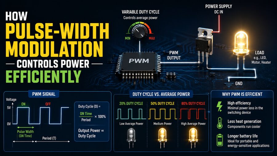

Pulse-Width Modulation, commonly known as PWM, is one of the most widely used techniques for controlling electrical power efficiently. It appears in motor controllers, LED dimmers, power supplies, battery chargers, audio amplifiers, robotics, electric vehicles, industrial automation, and countless embedded systems. 🔌🤖
Instead of reducing power by simply wasting excess energy as heat, PWM rapidly switches electrical power on and off. By changing how long the signal remains on during each switching cycle, a controller can regulate the average amount of power delivered to a load.
This seemingly simple idea is extremely powerful. A transistor acting as a switch can operate with relatively low losses because it spends most of its time either fully on or fully off. As a result, PWM can control motors, lights, heaters, and electronic circuits with much greater efficiency than many purely resistive or linear control methods.
🔄 What Is Pulse-Width Modulation?
Pulse-Width Modulation is a method of controlling the average voltage or power supplied to a device by varying the width of electrical pulses.
A PWM signal repeatedly switches between two states:
ON → OFF → ON → OFF
The signal may switch hundreds, thousands, or even millions of times per second, depending on the application.
The key parameter is called the duty cycle.
Duty cycle represents the percentage of each switching period during which the signal is on.
For example:
- 0% duty cycle = always off
- 25% duty cycle = on for one-quarter of each cycle
- 50% duty cycle = on for half of each cycle
- 75% duty cycle = on for three-quarters of each cycle
- 100% duty cycle = continuously on
If a 12-volt supply is switched using a 50% PWM duty cycle, the load experiences full 12-volt pulses half of the time and zero volts the other half.
For many loads, the effect is similar to receiving a lower average amount of power.
📊 Understanding Duty Cycle
Duty cycle can be expressed mathematically as:
Duty Cycle (%) = (ON Time ÷ Total Period) × 100
Suppose a PWM signal has a total period of 10 milliseconds.
If the signal stays on for 6 milliseconds and off for 4 milliseconds:
Duty Cycle = (6 ÷ 10) × 100 = 60%
Increasing the duty cycle generally increases the power delivered to the load.
Decreasing the duty cycle reduces it.
This gives electronic controllers extremely precise control over energy delivery.
⏱️ PWM Frequency
Another important PWM parameter is frequency.
Frequency describes how many complete on-off cycles occur each second and is measured in hertz (Hz).
For example:
- 100 Hz = 100 switching cycles per second
- 1 kHz = 1,000 cycles per second
- 20 kHz = 20,000 cycles per second
The appropriate frequency depends on the application.
LED lighting may use frequencies high enough that the human eye does not perceive flickering.
Motor controllers often use frequencies selected to balance switching losses, acoustic noise, motor characteristics, and control performance.
Power converters can operate from tens of kilohertz to hundreds of kilohertz or even into the megahertz range.
💡 PWM in LED Brightness Control
One of the easiest ways to understand PWM is through LED dimming.
An LED can be turned fully on and fully off very rapidly.
If this switching occurs quickly enough, the human eye does not see individual flashes. Instead, it perceives an average brightness.
At a low duty cycle, the LED is on only briefly during each cycle and appears dim.
At a high duty cycle, it remains on longer and appears brighter.
For example:
20% duty cycle → relatively dim
50% duty cycle → medium brightness
90% duty cycle → very bright
The LED itself may still receive its normal operating current while on. Brightness is controlled by changing the fraction of time it is energized.
This can be more efficient and predictable than trying to reduce brightness using large resistive losses.
⚙️ PWM in DC Motor Speed Control
PWM is also commonly used to control the speed of DC motors.
A motor connected directly to a power supply receives full voltage and tends to operate near its available speed under load.
With PWM, a transistor repeatedly connects and disconnects the motor from the supply.
At a low duty cycle, the motor receives less average power.
At a higher duty cycle, it receives more.
Because motors have mechanical inertia and electrical inductance, they do not stop and restart during every pulse. Instead, the rapid electrical switching produces a relatively smooth mechanical response.
The result is efficient speed control. 🚗⚙️
PWM is widely used in:
- Cooling fans
- Pumps
- Robotics
- Electric tools
- Conveyor systems
- Automotive actuators
- Small electric vehicles
🔋 Why PWM Is More Efficient Than Simple Resistive Control
Imagine controlling a motor’s speed using a variable resistor.
The resistor could reduce the voltage reaching the motor, but the unwanted electrical energy would be converted into heat inside the resistor.
That wastes power.
PWM takes a different approach.
The electronic switching device—usually a transistor such as a MOSFET—is operated mostly in two conditions.
When fully off, almost no current flows.
When fully on, the voltage drop across a well-selected transistor can be very small.
Electrical power loss is approximately:
P = V × I
If either voltage across the switching device or current through it is very small, its power dissipation can also be relatively low.
This is one of the central reasons switching power control can achieve high efficiency.
🔌 The Role of MOSFETs
Modern PWM circuits frequently use MOSFETs, or Metal-Oxide-Semiconductor Field-Effect Transistors.
A MOSFET functions as a fast electronic switch.
A controller sends a PWM waveform to its gate, causing the MOSFET to rapidly switch current through the load.
MOSFETs are especially useful because they can:
- Switch rapidly
- Handle substantial current
- Have low resistance when fully on
- Be controlled electronically
- Achieve high efficiency
For higher voltages or larger power levels, other semiconductor devices such as IGBTs or specialized power transistors may be used.
🔥 Why Switching Is Not Completely Lossless
PWM is highly efficient, but real switching devices are not perfect.
Some energy is still lost.
The two major categories are conduction losses and switching losses.
Conduction losses occur while a transistor is on because it still has some electrical resistance or voltage drop.
Switching losses occur during transitions between on and off states.
For a very brief period during each transition, both significant voltage and current may exist across the transistor.
This produces heat.
If PWM frequency becomes extremely high, the transistor performs many more transitions per second, which can increase switching losses.
Engineers must therefore select switching frequency carefully.
🌀 Inductive Loads and Flyback Current
Motors, relays, and many other electrical loads contain inductance.
An inductor resists sudden changes in current.
When a transistor suddenly switches off an inductive load, the current cannot instantly fall to zero.
Instead, the collapsing magnetic field can create a large voltage spike.
This phenomenon can damage electronic components if it is not controlled.
Engineers often use a flyback diode, freewheeling diode, or more advanced switching circuitry to provide a safe path for the inductive current.
In motor-control systems, this current path is an essential part of efficient PWM operation.
🎛️ How Microcontrollers Generate PWM
Microcontrollers frequently contain dedicated hardware timers capable of generating PWM signals.
The processor configures values such as:
- PWM frequency
- Duty cycle
- Output channel
- Timer period
- Compare value
Once configured, dedicated timer hardware can generate the waveform automatically.
This is much more precise than repeatedly turning an output pin on and off using software instructions.
A microcontroller can therefore control several PWM outputs while simultaneously performing other tasks.
Arduino boards, industrial controllers, automotive electronic control units, and embedded systems all make extensive use of this capability. 🤖
📐 PWM Resolution
PWM controllers also have a property known as resolution.
Resolution determines how many different duty-cycle levels can be selected.
An 8-bit PWM controller can usually represent:
2⁸ = 256 levels
A 12-bit system can represent:
2¹² = 4,096 levels
Greater resolution allows finer control.
For example, high-resolution PWM can provide smoother LED dimming or more precise motor control.
However, increasing resolution can sometimes affect the maximum available switching frequency depending on the timer architecture.
🔊 PWM and Audible Noise
PWM frequency can affect whether a system produces audible sounds.
Human hearing generally extends up to roughly 20 kHz, although sensitivity varies considerably.
If a motor controller operates at a few kilohertz, mechanical parts may vibrate at or near the switching frequency, creating an audible whine.
Designers may select frequencies above much of the audible range to reduce this problem.
However, simply increasing frequency is not always ideal because higher switching frequencies can increase power losses.
Engineering PWM systems therefore often involves a compromise between:
- Noise
- Efficiency
- Control precision
- Component heating
- Electromagnetic interference
🔌 PWM in Switching Power Supplies
PWM is fundamental to many switch-mode power supplies.
A switching regulator controls energy transfer by rapidly switching transistors.
The duty cycle determines how much energy is delivered to the output.
For example, a buck converter can reduce a higher DC voltage to a lower DC voltage.
Its control circuit monitors the output voltage.
If the output drops below the desired level, the controller can increase the PWM duty cycle.
If the output rises too high, it can reduce the duty cycle.
This creates a closed-loop control system that maintains a stable output despite changing input voltage or load conditions.
📱 Why PWM Matters in Portable Electronics
Smartphones, laptops, tablets, wireless devices, and other battery-powered electronics depend heavily on efficient power conversion.
Linear regulators can be useful for certain tasks, but when large voltage differences and significant currents are involved, they may waste considerable energy as heat.
PWM-based switching converters can often achieve much higher efficiency.
Higher efficiency means:
- Longer battery life
- Less heat
- Smaller cooling requirements
- Greater device reliability
- More compact power electronics
This makes PWM an important technology in portable electronics. 🔋📱
🚗 PWM in Electric Vehicles
Electric vehicles use sophisticated switching techniques closely related to PWM to control enormous amounts of electrical power.
A battery supplies DC electricity, but traction motors may require carefully controlled multiphase currents.
A power inverter uses high-power semiconductor switches to create the required waveforms.
By precisely controlling switching patterns, the inverter can regulate motor:
- Speed
- Torque
- Direction
- Efficiency
Modern motor-control methods are more complex than simple single-channel PWM, but PWM remains a fundamental concept behind power-electronic switching.
The same general principle also appears in EV auxiliary systems, pumps, fans, heaters, and DC-DC converters. 🚘⚡
☀️ PWM in Solar and Battery Systems
PWM can also appear in renewable-energy systems.
Some simpler solar charge controllers use PWM to regulate charging between photovoltaic panels and batteries.
More sophisticated systems often use Maximum Power Point Tracking (MPPT) converters, which themselves rely on high-frequency switching techniques to efficiently convert power.
Battery management and charging circuits may use PWM-controlled power stages to regulate voltage and current.
This allows charging systems to adapt to changing battery conditions.
🔥 PWM for Heating Control
PWM is not limited to motors and lights.
Electrical heaters can also be controlled using duty-cycle-based switching.
Suppose a heater is rated for 1,000 watts.
If it is powered for approximately half of each sufficiently long control interval, its average delivered power can approach 500 watts, depending on system behavior.
Heating elements have significant thermal inertia, so their temperature does not immediately fall every time power switches off.
This makes duty-cycle control particularly practical for:
- Industrial heaters
- Soldering stations
- 3D-printer heaters
- Ovens
- Temperature-controlled equipment
🎵 PWM in Audio Electronics
PWM concepts are also used in Class D audio amplifiers.
Instead of operating output transistors continuously in partially conducting states, a Class D amplifier switches them rapidly.
The switching waveform represents the audio information.
A filter and the loudspeaker’s electrical behavior help recover the desired audio signal.
Because the output transistors operate primarily as switches, Class D amplifiers can achieve very high efficiency.
This makes them popular in:
- Smartphones
- Wireless speakers
- Car audio systems
- Home theater equipment
- Battery-powered audio products
🌊 Filtering a PWM Signal
Sometimes the load responds naturally to the average effect of PWM.
A motor’s inductance and mechanical inertia, for instance, help smooth rapid pulses.
In other applications, engineers intentionally use filters.
A low-pass filter can reduce the high-frequency switching components and produce a smoother average voltage.
A simple filter might contain resistors, capacitors, or inductors.
This allows PWM to be used as a low-cost method of approximating an analog output from a digital controller.
📡 Electromagnetic Interference
Rapid switching produces fast changes in voltage and current.
These transitions can generate electromagnetic interference, commonly called EMI.
Uncontrolled EMI can interfere with:
- Radios
- Sensors
- Communication systems
- Nearby electronic circuits
Engineers reduce these effects through techniques such as:
- Careful circuit-board layout
- Proper grounding
- Shielding
- Filtering
- Controlled switching speeds
- Short current paths
This is especially important in automotive, aerospace, medical, and industrial electronics.
🧠 Closed-Loop PWM Control
PWM becomes even more useful when combined with sensors and feedback.
Consider a cooling fan.
A temperature sensor measures the system’s temperature.
The controller compares that measurement with a target value.
If the system becomes hotter, it increases the fan’s PWM duty cycle.
If the system cools, it decreases the duty cycle.
The basic loop becomes:
Sensor → Controller → PWM Signal → Device → New Measurement
This type of feedback control is common throughout engineering.
It allows machines to automatically adjust their power consumption according to actual operating conditions.
🏭 Industrial Applications of PWM
Industrial automation systems use PWM extensively.
Applications include:
- Motor drives
- Pumps
- Fans
- Solenoid valves
- Heating equipment
- Welding systems
- Power converters
- Robotic actuators
Efficient power control can significantly reduce operating costs in factories because motors and other electrical loads often consume large amounts of energy.
Advanced industrial drives may adjust power continuously according to production demand rather than operating equipment at full power all the time.
⚖️ PWM Versus Analog Voltage Control
PWM and traditional analog control can sometimes achieve similar external results, but their electrical behavior is different.
Analog control may continuously adjust a voltage to an intermediate value.
PWM instead alternates between two or more discrete states.
For example, an analog system might supply an LED with a steady reduced current.
A PWM system might deliver full current during short pulses and no current between them.
Neither technique is universally superior.
Analog control can be useful when extremely low electrical noise is important.
PWM is often preferred when high efficiency, digital control, and substantial power handling are priorities.
🚀 Advantages of PWM
PWM has become widespread because it offers several valuable characteristics:
- ⚡ High energy efficiency
- 🎛️ Precise power control
- 🤖 Easy integration with digital controllers
- 🔥 Reduced heat generation compared with many linear methods
- 🔋 Better battery utilization
- 📐 Fine adjustment through duty-cycle control
- 🚗 Excellent compatibility with motors and power electronics
- 💡 Effective LED dimming
These advantages allow relatively small electronic circuits to control surprisingly large amounts of power.
⚠️ Limitations and Engineering Challenges
PWM also introduces challenges.
Rapid switching can create:
- Electrical noise
- EMI
- Audible motor noise
- Voltage spikes
- Switching losses
- Thermal stress
- Harmonic currents
The system therefore requires correct transistor selection, thermal design, filtering, switching frequency, gate-drive circuitry, and protection components.
A poorly designed PWM circuit can be inefficient despite using an inherently efficient control technique.
The quality of the overall engineering remains crucial.
🔬 The Future of PWM Power Electronics
PWM continues to evolve alongside semiconductor technology.
Modern power electronics increasingly use advanced materials such as silicon carbide (SiC) and gallium nitride (GaN).
These semiconductor technologies can switch faster and operate efficiently at demanding voltages and temperatures.
Higher switching speeds can enable smaller transformers, inductors, and filters.
As a result, future power converters can become:
- Smaller
- Lighter
- More efficient
- More power-dense
These improvements are particularly valuable for electric vehicles, renewable energy, data centers, aerospace systems, and fast chargers. 🚀
✨ Conclusion
Pulse-Width Modulation controls electrical power by rapidly switching a supply on and off and adjusting the proportion of time it remains on.
That proportion—the duty cycle—determines how much average energy reaches the load.
At 20% duty cycle, relatively little energy is delivered. At 80%, considerably more is delivered. By continuously adjusting duty cycle, electronic controllers can precisely regulate motors, LEDs, heaters, power supplies, and many other devices.
The major efficiency advantage comes from using power transistors primarily as switches. When a transistor is fully off, current is nearly zero. When it is fully on, its voltage drop can be very small. This can reduce the energy that would otherwise be wasted as heat in a linear control element.
PWM is therefore a foundational technology in modern electronics. ⚡
From adjusting the brightness of a small LED to controlling the traction motor of an electric vehicle, the same basic idea applies: deliver full electrical power in carefully timed pulses instead of continuously wasting unwanted power.
With proper switching devices, feedback control, filtering, and thermal design, PWM provides a remarkably efficient and precise way to control energy—one rapid pulse at a time. 🔌⚙️