
Electronic devices rarely operate from a single convenient voltage. A battery may supply 12 volts, while a microcontroller needs 3.3 volts. A solar panel may produce 18 volts, while a battery charger requires a carefully controlled 24 volts. An electric vehicle may have a high-voltage battery pack but still need lower voltages for lights, sensors, computers, and communication modules.
Simply connecting these components together would not work. 🔋⚙️
The solution is a family of circuits known as DC-DC converters. Two of the most fundamental types are the buck converter, which reduces DC voltage, and the boost converter, which increases DC voltage.
Unlike simple resistors or linear regulators, switching converters can change voltage with high efficiency because they transfer energy using rapidly switched transistors, inductors, capacitors, and control circuits rather than deliberately turning excess electrical energy into heat.
Understanding buck and boost converters reveals one of the most important ideas in modern power electronics: voltage can be transformed efficiently even when the source and load are both DC.
🔌 What Is a DC-DC Converter?
A DC-DC converter is an electronic circuit that accepts one DC voltage and produces another DC voltage.
For example:
12 V DC → 5 V DC
or:
5 V DC → 12 V DC
The input and output are both direct current, but the voltage level changes.
The two basic converter types are:
- Buck converter — steps voltage down ⬇️
- Boost converter — steps voltage up ⬆️
More advanced circuits can combine both functions, but buck and boost topologies provide the foundation for understanding switching power supplies.
⬇️ What Is a Buck Converter?
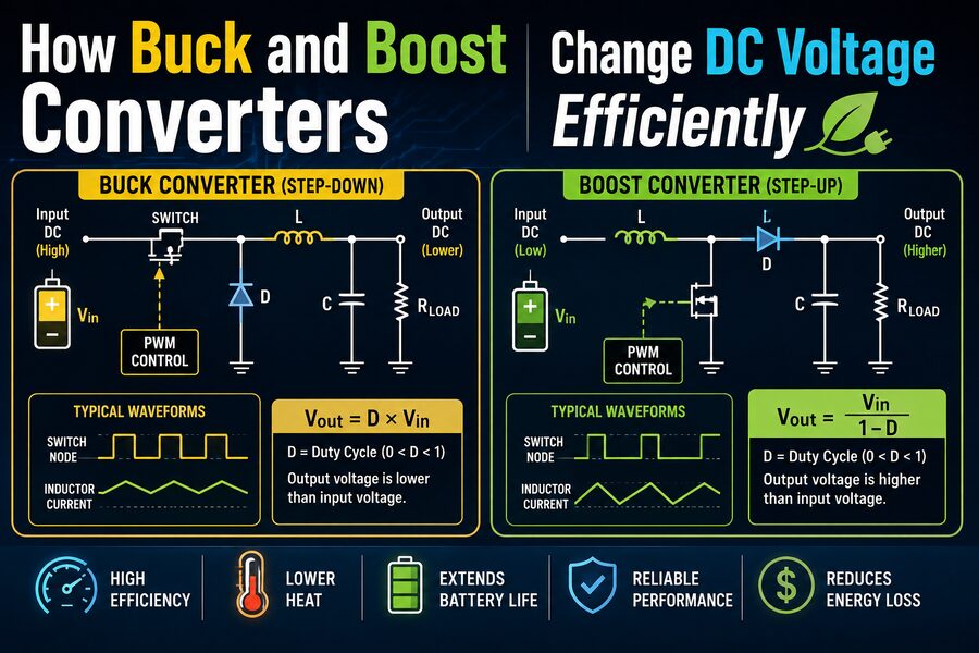
A buck converter reduces a higher DC input voltage to a lower DC output voltage.
For example:
12 V → 5 V
or:
48 V → 12 V
Buck converters are widely used in:
💻 Computers
📱 Smartphones
🚗 Vehicles
🔋 Battery-powered devices
🏭 Industrial electronics
🛰️ Aerospace systems
📡 Communication equipment
Modern processors are a perfect example.
A computer power supply might provide 12 volts to the motherboard, but the CPU itself may require approximately 1 volt.
Specialized buck converters near the processor reduce the voltage efficiently while delivering very large currents.
⚙️ The Main Parts of a Buck Converter
A basic buck converter contains several important components:
🔲 Switching transistor
Usually a MOSFET that rapidly turns current on and off.
🌀 Inductor
Stores energy temporarily in a magnetic field.
🔋 Capacitor
Smooths the output voltage.
➡️ Diode or synchronous MOSFET
Provides a path for current when the main switch is off.
🧠 Controller
Adjusts switching behavior to maintain the desired output voltage.
The key to efficient conversion is that the transistor is usually operated primarily in one of two states:
Fully ON or Fully OFF.
This avoids the high losses that would occur if it continuously operated in a partially conducting condition.
🔄 How a Buck Converter Works
A buck converter repeatedly alternates between two main operating states.
1️⃣ Switch ON
When the main transistor turns on:
Input source → transistor → inductor → load
Current begins flowing through the inductor.
The inductor stores energy in its magnetic field while also supplying current to the load.
Because the input voltage is higher than the output voltage, the inductor current generally increases during this interval.
2️⃣ Switch OFF
When the transistor turns off, the source is temporarily disconnected from the inductor.
However, current through an inductor cannot change instantly.
The magnetic field begins collapsing and continues pushing current toward the load.
A diode or second MOSFET provides the current path.
The inductor now releases some of its stored energy.
The output capacitor helps smooth the voltage during the switching process.
This cycle repeats thousands, hundreds of thousands, or even millions of times per second. ⚡
⏱️ Duty Cycle Controls the Output Voltage
The amount of time the switching transistor remains on during each switching cycle is called the duty cycle.
If a switching period lasts 10 microseconds and the transistor is on for 5 microseconds:
Duty cycle = 50%
For an ideal buck converter operating in continuous conduction:
Vout ≈ D × Vin
where:
Vout= output voltageVin= input voltageD= duty cycle
Suppose:
Vin = 12 V
and:
D = 0.5
Then:
Vout ≈ 6 V
If the duty cycle falls to 25%:
Vout ≈ 3 V
The control system therefore regulates output voltage by adjusting how long the transistor stays on during each cycle.
This technique is commonly called Pulse-Width Modulation, or PWM. 📊
🌀 Why the Inductor Is So Important
The inductor is central to switching conversion.
An inductor resists rapid changes in current.
When current increases, energy is stored in a magnetic field.
The stored energy is approximately:
E = ½LI²
where:
E= stored energyL= inductanceI= current
When the switch turns off, the inductor releases this energy.
This behavior allows the converter to move energy between the source and load in controlled packets rather than dissipating unwanted voltage as heat.
🔋 Why the Capacitor Is Needed
The switching waveform inside a converter is not naturally smooth.
Without filtering, the output voltage would contain large fluctuations.
The capacitor stores electrical charge and helps maintain a steady output.
When converter current temporarily exceeds what the load requires, the capacitor charges.
When converter current drops below the load demand, the capacitor supplies additional current.
Together:
Inductor smooths current 🌀
and:
Capacitor smooths voltage 🔋
This LC combination allows a rapidly switching circuit to produce a relatively stable DC output.
⬆️ What Is a Boost Converter?
A boost converter performs the opposite job.
It increases a lower DC voltage to a higher DC voltage.
Examples include:
5 V → 12 V
12 V → 24 V
200 V → 400 V
Boost converters are commonly found in:
🔋 Battery systems
☀️ Solar power electronics
🚗 Electric vehicles
💡 LED drivers
📱 Portable devices
⚡ Power-factor correction circuits
They are especially useful when the available source voltage is too low for the load.
🔄 How a Boost Converter Raises Voltage
At first, it may seem impossible to get a higher voltage than the battery provides.
But the inductor makes it possible.
A basic boost converter uses:
- Inductor
- Switching transistor
- Diode
- Capacitor
- Controller
Its operation also alternates between two states.
1️⃣ Boost Switch ON
When the transistor turns on, current flows:
Source → inductor → transistor → ground
The inductor current increases.
Energy is stored in the inductor’s magnetic field. 🌀
During this interval, the diode prevents the output capacitor from discharging backward through the switch.
The capacitor temporarily supplies the load.
2️⃣ Boost Switch OFF
When the transistor turns off, the inductor resists the sudden reduction in current.
Its magnetic field collapses, producing a voltage that adds to the input voltage.
Now the current flows through the diode into the output capacitor and load.
The output therefore receives energy from both:
Input source + collapsing inductor field
This allows the output voltage to rise above the input voltage.
🧮 Boost Converter Voltage Relationship
For an ideal boost converter in continuous conduction:
Vout ≈ Vin / (1 − D)
Suppose:
Vin = 5 V
and:
D = 0.5
Then:
Vout ≈ 5 / (1 − 0.5)
which gives:
10 V
If the duty cycle increases, the ideal output voltage rises.
For example:
D = 0.75
would theoretically produce:
Vout = 4 × Vin
Real converters are limited by losses, component ratings, current limits, and control stability, so engineers cannot increase duty cycle indefinitely.
🔥 Why Not Just Use a Resistor?
Suppose a circuit needs 5 volts from a 12-volt source.
A resistor could reduce voltage under a specific load condition, but it would waste energy as heat and the output voltage would vary as current changes.
This makes it unsuitable for most regulated power applications.
A linear regulator provides much better voltage control but still dissipates excess voltage as heat.
For example, imagine:
Input = 12 V
Output = 5 V
Load current = 2 A
The load receives:
5 V × 2 A = 10 W
A linear regulator dissipates approximately:
(12 V − 5 V) × 2 A = 14 W
as heat. 🌡️
The regulator is therefore losing more power than the load itself uses.
A high-efficiency buck converter might instead operate at around 90% or better under suitable conditions, dramatically reducing heat generation.
⚡ Why Switching Converters Are Efficient
Power is:
P = V × I
A switching converter ideally conserves power, apart from losses.
So if voltage decreases, current capability can increase.
For example:
12 V × 1 A = 12 W
An ideal buck converter could theoretically produce:
6 V × 2 A = 12 W
Similarly, a boost converter that doubles voltage must generally reduce available output current accordingly.
This is an important point:
A boost converter does not create energy.
It trades current for voltage while conserving energy as closely as practical.
Real systems always lose some power as heat.
📈 What Does 95% Efficiency Mean?
Suppose a converter receives:
100 W
and delivers:
95 W
to the load.
Its efficiency is:
95%
The remaining:
5 W
is lost as heat.
Efficiency is calculated as:
Efficiency = Pout / Pin × 100%
High efficiency matters because lower losses mean:
🌡️ Less heat
🔋 Longer battery runtime
📦 Smaller cooling systems
💰 Lower energy cost
⚙️ Smaller components in some designs
📈 Greater power density
This is why switching converters are essential in portable and high-power electronics.
🔥 Where Converter Losses Come From
Real buck and boost converters are never 100% efficient.
Losses come from several sources.
⚡ MOSFET conduction losses
When a transistor is on, it has a small resistance.
Current flowing through that resistance produces:
P = I²R
loss.
🔄 Switching losses
During transistor turn-on and turn-off, voltage and current briefly overlap.
This dissipates energy every switching cycle.
🌀 Inductor losses
Inductor wire has resistance, producing copper loss.
The magnetic core also experiences hysteresis and eddy-current losses.
➡️ Diode losses
Traditional diodes have a forward voltage drop.
At high current, this can waste significant power.
🔋 Capacitor losses
Real capacitors have equivalent series resistance, or ESR.
Ripple current flowing through that resistance creates heat.
🔁 What Is a Synchronous Buck Converter?
Traditional buck converters use a diode during the switch-off interval.
But the diode’s forward voltage causes power loss.
A synchronous buck converter replaces the diode with another controlled MOSFET.
Since a properly selected MOSFET can have a very low on-resistance, conduction losses can be significantly reduced.
This is especially important in low-voltage, high-current applications such as:
🧠 CPU power supplies
🎮 Graphics cards
📱 Mobile electronics
📡 Telecommunications systems
Modern high-performance buck converters commonly use synchronous rectification.
🎛️ Feedback Keeps the Voltage Stable
A converter cannot simply operate at one fixed duty cycle and assume the output will remain correct.
Input voltage changes.
Loads change.
Components heat up.
The system therefore uses feedback control.
A typical control loop works like this:
Measure output voltage → compare with reference → calculate error → adjust PWM duty cycle
Suppose the output begins falling below the target.
The controller may increase energy transfer.
If the output rises too high, it reduces energy transfer.
This happens continuously, allowing the converter to maintain a regulated output even as operating conditions change. 🧠
📉 What Is Ripple?
The output of a switching converter is not perfectly constant.
A small periodic variation remains.
This is called voltage ripple.
Ripple depends on:
- Switching frequency
- Inductance
- Capacitance
- Load current
- Capacitor ESR
- Control strategy
- Circuit layout
Sensitive electronics may require extremely low ripple.
Engineers can reduce it by using appropriate inductors, capacitors, filtering, switching frequencies, and board layouts.
⏩ Why Use High Switching Frequencies?
Higher switching frequencies can allow smaller inductors and capacitors.
That helps make converters physically compact.
However, increasing switching frequency also increases switching losses.
So engineers face another tradeoff:
Higher frequency → smaller components but potentially lower efficiency
Lower frequency → larger components but potentially lower switching losses
Modern designs choose a frequency that balances:
📦 Size
⚡ Efficiency
🌡️ Heat
📡 Electromagnetic interference
💰 Cost
Some compact converters operate in the megahertz range.
📡 Electromagnetic Interference Is a Major Challenge
Rapidly switching voltage and current creates electrical noise.
This can generate electromagnetic interference, or EMI.
Poor converter design can interfere with:
📻 Radios
📡 Wireless communication
🎛️ Sensors
🧠 Digital circuits
🎤 Audio electronics
Engineers control EMI using:
- Careful PCB layout
- Short switching-current loops
- Ground planes
- Input filters
- Shielding
- Snubber circuits
- Controlled switching speeds
Good circuit layout can be just as important as choosing the right components.
🔋 Buck Converters in Battery-Powered Electronics
Imagine a lithium-ion battery whose voltage varies from approximately:
4.2 V when fully charged
to:
around 3 V when nearly discharged
A microcontroller might require:
1.8 V
Because battery voltage remains higher than the required rail, a buck converter can step it down efficiently.
This allows the electronic device to extract useful energy from the battery while minimizing power loss.
Smartphones contain numerous DC-DC converters because different components may require different supply voltages.
☀️ Boost Converters in Solar Systems
Solar panels produce voltages that vary with sunlight, temperature, and load.
A boost converter can increase panel voltage to a level appropriate for:
🔋 Battery charging
⚡ DC bus systems
🏠 Inverters
📡 Remote electronics
Solar systems often combine DC-DC conversion with Maximum Power Point Tracking, or MPPT.
The converter continuously changes its operating conditions so the solar panel can operate near the point where it produces maximum available power.
This is a powerful example of power electronics doing more than simply changing voltage.
🚗 Buck and Boost Converters in Electric Vehicles
Electric vehicles contain multiple voltage domains.
The traction battery may operate at hundreds of volts.
But accessories may require:
48 V, 12 V, 5 V, 3.3 V, or even lower voltages.
High-voltage DC-DC converters step battery-pack voltage down for conventional low-voltage systems.
Other converter stages may boost voltage for specific motor-drive or charging requirements.
Without efficient DC-DC conversion, modern EV electrical architecture would be far less practical. 🔋🚗
🔄 What Is a Buck-Boost Converter?
Sometimes the input voltage can be either higher or lower than the required output.
For example, a battery might vary between:
8 V and 14 V
while a circuit needs a stable:
12 V
When the battery is above 12 V, the converter must step down.
When it is below 12 V, the converter must step up.
A buck-boost converter can perform both functions.
Several architectures exist, including:
- Inverting buck-boost
- SEPIC
- Ćuk converters
- Four-switch synchronous buck-boost
These topologies are useful in battery systems where source voltage changes significantly during operation.
🧠 Continuous and Discontinuous Conduction Modes
Engineers also classify converters according to inductor current behavior.
🌀 Continuous Conduction Mode
The inductor current never falls completely to zero during each switching cycle.
This is common at moderate or heavy loads.
0️⃣ Discontinuous Conduction Mode
The inductor current falls to zero for part of the switching cycle.
This often occurs at light load.
These modes affect:
- Voltage relationships
- Control design
- Ripple
- Efficiency
- Dynamic response
Modern controllers may deliberately change operating modes to improve efficiency across a wide load range.
🌙 Power-Saving Modes at Light Load
A converter designed to power a smartphone cannot waste large amounts of energy when the phone is idle.
At very low load currents, ordinary fixed-frequency PWM operation may become inefficient.
Controllers may therefore enter modes such as:
💤 Pulse skipping
⚡ Pulse-frequency modulation
🔄 Burst mode
🌙 Sleep mode
These strategies reduce switching activity when little power is needed.
The goal is to minimize the converter’s own energy consumption.
🛡️ Protection Features in Modern Converters
DC-DC converters frequently include extensive protection circuitry.
Possible protections include:
⚠️ Overcurrent protection
🔥 Overtemperature shutdown
📈 Overvoltage protection
📉 Undervoltage lockout
🔌 Short-circuit protection
⏳ Soft-start control
Soft-start gradually increases output voltage after startup, preventing a large initial surge current from charging the output capacitor too rapidly.
These protections are especially important in high-power systems where a fault could damage expensive electronics.
📐 Why PCB Layout Matters
A converter that looks correct on a circuit diagram can still perform badly if the printed circuit board is poorly designed.
Switching currents can change very rapidly.
The paths carrying these currents should therefore be kept short and compact.
Engineers carefully position:
🔲 MOSFETs
➡️ Diodes
🔋 Capacitors
🌀 Inductors
🧠 Controller ICs
Poor layout can cause:
📡 EMI
⚡ Voltage spikes
🌡️ Excess heating
📉 Reduced efficiency
🧠 Control instability
In power electronics, physical geometry is part of the electrical design.
💻 How Engineers Design a Converter
A typical converter design process includes:
- Determine input-voltage range
- Define required output voltage
- Determine maximum output current
- Choose switching topology
- Select switching frequency
- Calculate inductor value
- Select output capacitors
- Choose MOSFETs and diodes
- Design feedback compensation
- Evaluate thermal performance
- Analyze EMI
- Test under load and transient conditions
Engineers must ensure the design works not only under normal conditions but also during startup, shutdown, sudden load changes, and electrical faults.
🚀 Why Buck and Boost Converters Are Everywhere
The modern world depends on many different DC voltage levels.
Processors require extremely low voltages.
Batteries produce voltages that change with state of charge.
Solar panels vary with sunlight.
Electric vehicles use both low- and high-voltage electrical systems.
LEDs require controlled current.
Communication equipment requires quiet, regulated power.
Buck and boost converters make all of these systems practical by efficiently moving energy between voltage levels.
They are hidden inside:
📱 Phones
💻 Laptops
🎮 Game consoles
🚗 Cars
☀️ Solar inverters
🔌 USB chargers
🏭 Industrial equipment
🛰️ Satellites
Most users never see them, yet they operate continuously whenever modern electronics are powered.
✅ Conclusion
Buck and boost converters are fundamental building blocks of modern power electronics.
A buck converter lowers DC voltage by rapidly switching the input and using an inductor and capacitor to average the resulting energy into a stable lower-voltage output.
A boost converter increases DC voltage by storing energy in an inductor and then releasing that energy so its voltage adds to the input source.
Both rely on rapid switching rather than continuous energy dissipation, which is why they can achieve very high efficiency. ⚡
Their control systems continuously adjust switching duty cycle in response to changing input voltage, load current, and operating conditions.
The result is a compact and efficient way to provide exactly the voltage electronic systems need.
Whether inside a smartphone, electric vehicle, solar installation, computer motherboard, or industrial controller, buck and boost converters perform the same essential task:
They reshape DC electrical power into a more useful voltage while wasting as little energy as possible. 🔋⚙️
That simple capability is one of the reasons modern electronics can be smaller, cooler, more efficient, and more powerful than ever before.