
Digital circuits are built around a simple idea: a signal is interpreted as either LOW or HIGH, usually corresponding to binary 0 and 1. In the real world, however, electrical signals are rarely perfectly clean. Sensors, switches, long wires, motors, power supplies, and electromagnetic interference can all introduce noise. Instead of changing neatly from one voltage level to another, a signal may wobble, bounce, or fluctuate around the switching point. 📈📉
That creates a serious problem.
If an ordinary digital input sees a noisy voltage hovering near its threshold, it may rapidly switch back and forth between HIGH and LOW. A microcontroller could interpret one button press as several presses, a counter could register extra pulses, or a control circuit could behave unpredictably.
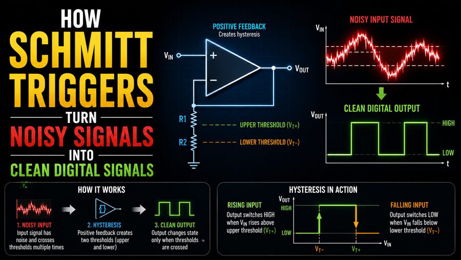
A Schmitt trigger solves this problem by introducing something called hysteresis. Rather than using one switching voltage for both rising and falling signals, it uses two different thresholds.
This seemingly small change can transform a messy analog waveform into a stable, clean digital signal. 🔧✨
🔍 What Is a Schmitt Trigger?
A Schmitt trigger is an electronic circuit with a digital-like output and two different input switching thresholds.
One threshold is used when the input voltage is rising, and another is used when the input voltage is falling.
These are commonly called:
- Upper threshold voltage
- Lower threshold voltage
Suppose a Schmitt trigger has:
- Upper threshold = 3.0 V
- Lower threshold = 2.0 V
If the input rises from 0 V, the output does not change state until the input reaches 3.0 V.
Once the output changes, the input can fall somewhat without causing another transition.
The output will not switch back until the voltage drops below 2.0 V.
The region between 2.0 V and 3.0 V is the hysteresis band. ⚡
That hysteresis is what makes the circuit resistant to noise.
🌊 The Problem With Noisy Signals
Imagine a sensor signal that is gradually rising toward a digital switching threshold of 2.5 V.
Ideally, it might look like:
0 V → 1 V → 2 V → 3 V → 5 V
But a real signal might behave more like:
2.3 V → 2.6 V → 2.4 V → 2.7 V → 2.45 V → 2.8 V
If an ordinary comparator switches at exactly 2.5 V, every time the signal crosses 2.5 V the output can change state.
The result might look like:
LOW → HIGH → LOW → HIGH → LOW → HIGH
instead of one clean transition.
This phenomenon is sometimes called chattering or multiple switching.
Digital circuits receiving this output may believe several events have occurred when there was really only one slow or noisy transition. 😵💫
⚖️ How Hysteresis Fixes the Problem
A Schmitt trigger deliberately separates the switching thresholds.
Using our previous example:
- Rising signal must exceed 3.0 V to switch HIGH.
- Falling signal must drop below 2.0 V to switch LOW.
Now imagine the input rises past 3.0 V and then fluctuates:
3.1 V → 2.8 V → 3.0 V → 2.7 V → 3.2 V
The output remains HIGH because none of these fluctuations fall below the lower 2.0 V threshold.
Small disturbances inside the hysteresis band are ignored. 🛡️
Only a sufficiently large change causes the circuit to switch again.
This gives the Schmitt trigger a kind of electrical “memory”: its present output depends not only on the current input voltage but also on whether the signal approached that voltage from above or below.
🧠 Why It Is Called Hysteresis
The term hysteresis describes systems whose output depends partly on their previous state.
In a simple comparator without hysteresis, the rule might be:
Input > 2.5 V → HIGH
Input < 2.5 V → LOW
There is only one boundary.
With a Schmitt trigger, the rule is different:
For a rising input:
Input > upper threshold → switch
For a falling input:
Input < lower threshold → switch back
Between those two thresholds, the circuit keeps its previous output state.
This creates a hysteresis loop when input and output behavior are plotted graphically. 🔄
🔧 Schmitt Trigger vs. Ordinary Comparator
A comparator compares two voltages and changes its output depending on which is larger.
For example, a comparator could compare an input signal against a 2.5 V reference.
If the input rises above 2.5 V, the output changes.
If it falls below 2.5 V, the output changes back.
This works well for fast, clean signals.
But if noise causes the voltage to repeatedly cross 2.5 V, the comparator output may oscillate.
A Schmitt trigger can be created by adding positive feedback to the comparator.
Positive feedback changes the effective reference voltage depending on the current output state.
This creates separate upper and lower thresholds.
So conceptually:
Comparator + positive feedback = Schmitt trigger behavior ⚡
➕ How Positive Feedback Creates Two Thresholds
Consider a comparator circuit in which part of the output voltage is fed back to the reference input.
When the output is HIGH, the feedback shifts the switching threshold in one direction.
When the output is LOW, the threshold moves in the other direction.
This means the circuit effectively asks for a larger input change before it allows itself to switch again.
For example:
When output is LOW:
Input must rise above 3 V
After switching HIGH:
Input must fall below 2 V
Because the output participates in determining the threshold, the circuit naturally develops hysteresis.
Positive feedback is therefore the key mechanism behind many analog Schmitt trigger circuits. 🔁
📈 Turning a Slow Signal Into a Sharp Digital Edge
Noise is not the only problem Schmitt triggers solve.
Some signals change very slowly.
Suppose a voltage from a light sensor gradually rises as sunlight becomes brighter.
A digital circuit may prefer an abrupt transition between LOW and HIGH.
A Schmitt trigger converts the slow-moving signal into a fast output transition once the upper threshold is reached.
Even if the input takes seconds to move from 1 V to 4 V, the output can switch almost instantly.
This produces a crisp digital edge that downstream logic circuits can process reliably. ⚡📊
🔘 Debouncing Mechanical Switches
Mechanical switches are a classic source of noisy digital signals.
When you press a physical push button, its contacts do not necessarily close once cleanly.
They may physically bounce against each other for a short period.
The electrical signal might appear as:
OFF → ON → OFF → ON → OFF → ON
even though the user pressed the button only once.
This is called switch bounce.
A Schmitt trigger can help clean up the signal, especially when combined with a resistor-capacitor, or RC, network.
The RC circuit smooths the bouncing transitions, while the Schmitt trigger converts the slowly changing voltage into a clean HIGH or LOW signal.
This technique is widely used in:
- Push buttons
- Keyboards
- Mechanical switches
- Limit switches
- Rotary encoders
🔘➡️⚡
⏱️ Using an RC Network With a Schmitt Trigger
An RC network contains a resistor and capacitor.
A capacitor does not change voltage instantaneously. Instead, it charges and discharges gradually.
If a switch bounces rapidly, the capacitor can smooth those fast fluctuations.
However, the capacitor creates another issue: the resulting voltage transition becomes slow.
A normal digital input may dislike such a slow transition.
A Schmitt trigger solves that problem.
The sequence becomes:
Bouncing switch → RC smoothing → slowly changing voltage → Schmitt trigger → clean digital edge
This combination is simple, inexpensive, and extremely useful.
🎛️ Cleaning Sensor Outputs
Many physical sensors naturally produce analog or noisy signals.
Examples include:
- Light sensors ☀️
- Temperature sensors 🌡️
- Magnetic sensors 🧲
- Pressure sensors
- Vibration sensors
- Proximity detectors
- Photodiodes
Suppose a light sensor controls an automatic outdoor lamp.
Without hysteresis, the lamp might rapidly turn ON and OFF at dusk because the sensor voltage is close to the switching point.
A car passing nearby, a cloud, or a small change in ambient light could repeatedly trigger the circuit.
With hysteresis, the lamp might turn ON when light falls below one level but not turn OFF again until brightness rises significantly above another level.
This prevents flickering.
The same concept appears in thermostats.
A heater might turn ON at 19°C and remain on until the temperature reaches 21°C instead of switching repeatedly around exactly 20°C.
Although thermostats can use different implementations, the control concept is essentially hysteresis. 🌡️
🖥️ Schmitt Trigger Inputs in Digital ICs
Many digital integrated circuits include Schmitt trigger inputs internally.
This allows them to safely receive signals that may have:
- Slow rise times
- Slow fall times
- Electrical noise
- Long cable interference
A famous logic family example includes devices such as Schmitt-trigger inverters.
A standard inverter produces the opposite logical state of its input.
For example:
LOW input → HIGH output
HIGH input → LOW output
A Schmitt-trigger inverter does the same thing but uses separate rising and falling thresholds.
This combines signal inversion and noise cleanup in one device. 🔄
🔌 Microcontrollers and Schmitt Trigger Inputs
Many microcontroller input pins also use some form of input hysteresis.
This makes them more resistant to small noise fluctuations.
When a digital sensor sends a signal over a wire, electrical interference could cause small voltage variations.
Without hysteresis, fluctuations near the input threshold might create false transitions.
Schmitt-trigger behavior helps ensure that a meaningful voltage change is required before the input changes logic state.
However, designers should still follow the voltage and timing specifications in the microcontroller’s datasheet because hysteresis does not eliminate every possible signal-integrity problem. 📘
📡 Improving Signals Over Long Wires
Long wires can behave like antennas.
They may pick up electromagnetic interference from:
- Motors
- Relays
- Switching power supplies
- Radio transmitters
- Fluorescent lighting
- Nearby power cables
A signal that began as a clean square wave may reach the receiving circuit with ringing, noise, or rounded edges.
A Schmitt trigger placed near the receiver can regenerate the signal.
Small noise fluctuations are ignored, while legitimate transitions crossing the hysteresis thresholds produce clean output edges.
This is one reason hysteresis is valuable at electrical interfaces. 📡⚡
🌀 Creating Oscillators With Schmitt Triggers
Schmitt triggers are not limited to cleaning signals.
They can also be used to build oscillators.
A simple circuit can combine:
- A Schmitt-trigger inverter
- A resistor
- A capacitor
The capacitor repeatedly charges and discharges between the Schmitt trigger’s upper and lower threshold voltages.
When it reaches the upper threshold, the output switches.
That causes the capacitor to begin moving in the opposite direction.
When it reaches the lower threshold, the output switches again.
This cycle repeats continuously.
The result is an oscillator that can generate a repeating waveform. 🔄⏱️
Such circuits can be useful for:
- Clock signals
- LED flashers
- Simple tone generators
- Timing circuits
📐 Inverting vs. Non-Inverting Schmitt Triggers
Schmitt triggers can be designed in both inverting and non-inverting configurations.
🔄 Inverting Schmitt Trigger
In an inverting design, increasing the input past the upper threshold can cause the output to go LOW.
Decreasing the input below the lower threshold then causes the output to go HIGH.
The output logic is inverted relative to the input.
➡️ Non-Inverting Schmitt Trigger
In a non-inverting design, crossing the upper threshold causes the output to go HIGH.
Falling below the lower threshold causes it to go LOW.
Both configurations use hysteresis; only the relationship between input and output changes.
📏 What Determines the Hysteresis Width?
The difference between the upper and lower switching thresholds is called the hysteresis width.
For example:
Upper threshold:
3.2 V
Lower threshold:
1.8 V
Hysteresis width:
3.2 V − 1.8 V = 1.4 V
A wider hysteresis band generally provides greater immunity to noise.
But making the hysteresis too wide may mean the input must change more than desired before the circuit responds.
Designers therefore choose thresholds based on:
- Expected noise amplitude
- Signal voltage range
- Required sensitivity
- Logic voltage levels
- Sensor characteristics
The right amount of hysteresis depends on the application. ⚖️
🛡️ Noise Margin and Reliable Logic
One major advantage of hysteresis is increased tolerance to noise around a switching threshold.
Suppose a system expects a clean HIGH signal around 5 V and a LOW signal around 0 V.
Noise of a few hundred millivolts might not matter when the signal is far from the switching thresholds.
The most dangerous situation occurs during a transition.
A Schmitt trigger prevents small voltage disturbances around that transition from repeatedly changing the output.
Once the output has switched, the input must travel all the way to the opposite threshold before another transition occurs.
This creates a protective dead zone against small disturbances. 🛡️
⚡ Why Fast Digital Edges Matter
Digital circuits are often designed to interpret signals that move quickly between valid LOW and HIGH regions.
Very slow edges can sometimes create problems such as:
- Increased switching uncertainty
- Multiple transitions
- Higher power consumption in certain logic circuits
- Greater sensitivity to noise
- Timing errors
A Schmitt trigger effectively converts a slow or imperfect analog transition into a fast logical change.
That makes downstream circuitry much easier to design reliably.
🔊 A Real-World Example: Audio Noise Detector
Imagine an audio-based circuit designed to detect whether sound exceeds a certain level.
The microphone produces a varying analog voltage.
If the detector used only a single comparator threshold, a sound hovering around that level could cause the output to rapidly switch:
ON → OFF → ON → OFF
Adding hysteresis creates two thresholds.
Perhaps:
- Output activates when sound rises above the high threshold.
- Output stays active until sound falls below the lower threshold.
Small changes around the boundary no longer matter.
The result is a much more stable detector. 🎤
🚗 Schmitt Triggers in Automotive Electronics
Vehicles contain electrically noisy environments.
Ignition systems, motors, alternators, pumps, injectors, and switching electronics can all generate interference.
Signals from switches and sensors may therefore require conditioning before reaching digital controllers.
Hysteresis can help prevent false switching caused by electrical noise.
Applications may include:
- Position detection
- Speed sensing
- Switch interfaces
- Control modules
- Sensor signal conditioning
Modern automotive electronics often include more sophisticated filtering as well, but Schmitt-trigger principles remain highly useful. 🚙⚡
🏭 Industrial Applications
Factories present even harsher electrical environments.
Large motors, contactors, variable-frequency drives, welding equipment, and long signal cables can produce significant interference.
Industrial control systems must distinguish real signals from noise.
Schmitt-trigger circuits may be used as part of interfaces involving:
- Limit switches
- Proximity sensors
- Encoders
- Alarm circuits
- Digital control inputs
By preventing uncertain voltages from producing repeated digital transitions, hysteresis improves reliability. 🏭
🆚 Schmitt Trigger vs. Filtering
It is important to understand that a Schmitt trigger is not exactly the same thing as a filter.
A conventional low-pass filter reduces rapidly changing components in a signal.
A Schmitt trigger instead makes a decision based on thresholds and history.
The two techniques are often combined.
For example:
Filter → reduce high-frequency noise
Schmitt trigger → convert remaining signal into stable logic
This can provide better results than either technique alone.
⚠️ What a Schmitt Trigger Cannot Fix
Schmitt triggers are extremely useful, but they are not magic.
If noise is larger than the hysteresis band, the circuit may still change state unexpectedly.
A Schmitt trigger also cannot correct:
- Incorrect voltage levels
- Severe electromagnetic interference
- Damaged signals
- Timing violations
- Grounding problems
- Excessive ringing that crosses both thresholds
In difficult environments, designers may need additional techniques such as:
- Shielded cables
- Differential signaling
- Proper grounding
- RC filtering
- Digital filtering
- Termination resistors
- Isolation
Reliable electronics often use several protective techniques together. 🔧
🧩 A Simple Way to Visualize the Concept
Imagine a door with two different rules.
To enter a room, you must push the door past a mark at 3 meters.
But once inside, you do not leave until you move back past a mark at 2 meters.
If you wander between 2 and 3 meters, nothing changes.
That middle region prevents constant switching.
A Schmitt trigger behaves similarly.
For a rising voltage:
Cross the upper threshold → change state
For a falling voltage:
Cross the lower threshold → change back
Inside the hysteresis region:
Keep the previous state.
This simple principle gives Schmitt triggers their remarkable resistance to noisy signals. 🚪⚡
✅ Conclusion
Schmitt triggers solve one of the fundamental problems in digital electronics: real-world signals are often messy, while digital logic expects clear decisions.
A normal comparator may switch repeatedly when a noisy or slowly changing input hovers around a single threshold. A Schmitt trigger avoids this by using two thresholds—one for rising signals and another for falling signals.
The difference between those thresholds creates hysteresis. 🔄
Once the output switches HIGH, small fluctuations cannot immediately force it LOW again. The input must cross the lower threshold first. Likewise, a LOW output remains stable until the rising input passes the upper threshold.
This simple technique can clean up switch bounce, stabilize sensor outputs, restore noisy signals traveling through wires, create reliable logic transitions, and even form the basis of simple oscillators.
Schmitt triggers appear in discrete comparator circuits, logic gates, microcontrollers, industrial electronics, automotive systems, sensor interfaces, and countless embedded devices.
Their usefulness comes from a powerful engineering idea: instead of forcing a noisy signal to make a decision at one exact voltage, provide enough separation between the ON and OFF points that small disturbances no longer matter. 🛡️⚡
By adding just a little hysteresis, a Schmitt trigger can take an uncertain, wobbling analog waveform and transform it into exactly what a digital circuit wants—a clean, stable HIGH or LOW signal. 📈➡️⬛⬜