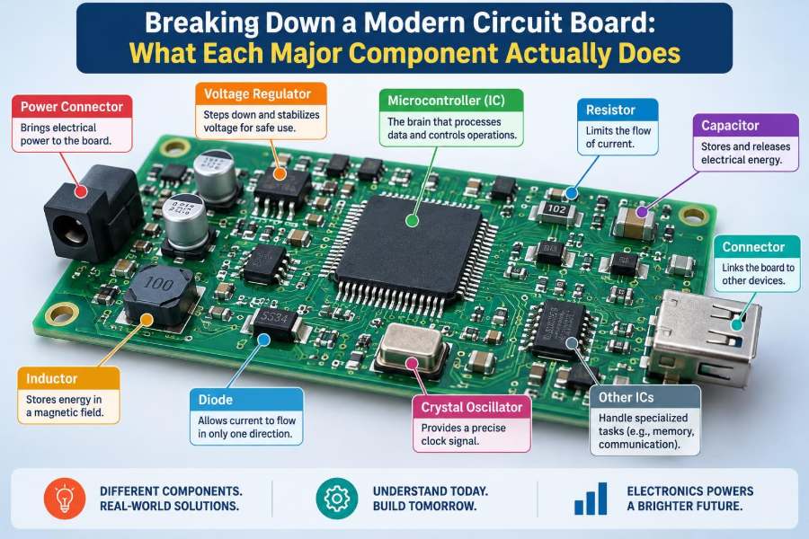

You open a laptop, charge a phone, start a car, or adjust a smart thermostat, and a circuit board quietly turns your action into a coordinated electrical response. The board may look like a crowded green, blue, or black rectangle, but its parts are not placed there at random.
Every component has a job: delivering energy, making decisions, storing settings, sensing the outside world, or moving information from one place to another. When one job is misunderstood, troubleshooting can become guesswork.
Learning to read a modern printed circuit board, or PCB, is useful well beyond repair work. It helps students connect circuit theory to real hardware and helps professionals diagnose failures, review designs, and communicate across electrical, mechanical, and software teams.
A board is best understood as a working system rather than a collection of isolated parts. Start with power, follow signals, and ask what each component must do for the product to behave as intended.
🧩 A Circuit Board Is a System, Not Just a Surface
A PCB is a mechanically supported network of conductive paths and mounted components. Its copper traces carry power and signals, while insulating material keeps intended connections separate.
The visible side rarely tells the whole story. Many boards contain several copper layers buried inside the laminate, allowing dense routing, controlled signal paths, and continuous reference planes for power and ground.
A practical first question is: where does energy enter, and where does information enter? Following those two paths reveals much of the board’s architecture.
🟩 The PCB Substrate Holds Everything Together
The rigid base is commonly made from FR-4, a glass-fiber-reinforced epoxy laminate. It provides stiffness, electrical insulation, and a stable platform for copper layers and soldered components.
Material choice matters at high frequency, high temperature, or in flexible products. A microwave board may use a low-loss laminate, while a wearable device may use a flexible polyimide circuit.
The substrate is not electrically invisible. Its dielectric properties influence capacitance, impedance, signal loss, and how quickly high-speed edges propagate through traces.
🟠 Copper Traces Are the Board’s Wiring
Traces are patterned copper conductors that replace many point-to-point wires. Wide traces are often used for higher current, while narrow traces commonly carry logic or analog signals.
Trace width alone does not determine whether a path is safe. Current, copper thickness, ambient temperature, allowed temperature rise, and whether the trace is on an outer or inner layer all affect its capacity.
On a simple board, traces can be followed visually. On a multilayer board, however, a connection may disappear into a via and continue on an internal layer.
🕳️ Vias Connect Copper Layers
A via is a plated hole that electrically joins copper features on different layers. It lets designers route a signal or power path through the board instead of around other traces.
Through vias run from the top to the bottom of the PCB. Blind and buried vias connect only selected layers and can save routing space, although they increase fabrication complexity and cost.
Vias also serve thermal purposes. A cluster beneath a power device can conduct heat into internal copper planes, reducing the device’s junction temperature.
🌍 Ground Planes Provide the Return Path
Ground is often treated as a universal zero-volt point, but on a real PCB it is a conductive network with resistance and inductance. High-frequency current returns along paths shaped by nearby reference planes.
A solid ground plane gives signals a short, predictable return path. It also reduces loop area, which helps control electromagnetic interference, or EMI.
Splitting a ground plane carelessly can force a fast signal’s return current to take a long detour. The result may be noise, radiation, or unexpected signal distortion even when the trace itself appears correctly routed.
🔋 Power Connectors Bring Energy onto the Board
Power may arrive through a barrel jack, USB connector, battery contacts, terminal block, board edge connector, or a cable harness. The connector determines mechanical fit, voltage capability, current rating, and sometimes communication features.
Near the entry point, designers commonly place protective and filtering parts before sensitive circuitry. This is where the board prepares for reversed wiring, voltage spikes, electrostatic discharge, and noise from the outside world.
Never assume a connector’s shape identifies its voltage. Similar-looking connectors can carry very different supplies, and incorrect probing can damage equipment or create a safety hazard.
🛡️ Input Protection Handles Real-World Abuse
External cables can bring electrostatic discharge, transients, accidental reverse polarity, and overcurrent conditions. Protection circuitry attempts to limit the damage before those events reach expensive integrated circuits.
Common approaches include fuses or resettable fuses for excessive current, transient-voltage suppressor diodes for spikes, reverse-polarity MOSFET arrangements, and common-mode chokes for cable-borne noise.
Protection always involves trade-offs. A device with very low clamping voltage may add capacitance that degrades a fast data line, while a fuse chosen too aggressively may trip during normal startup current.
⚡ Voltage Regulators Create Usable Power Rails
A product may receive 12 V from an adapter but need 5 V for peripherals, 3.3 V for digital logic, and a quieter voltage for an analog sensor. Voltage regulators generate and stabilize these separate rails.
A linear regulator drops excess voltage as heat. It is simple and can be low noise, but its efficiency becomes poor when the voltage difference and load current are large.
A switching regulator rapidly switches energy through inductors, capacitors, and semiconductor switches. It can be efficient, but it requires careful layout to control ripple, EMI, and transient behavior.
🌀 Inductors Store Energy Magnetically
Inductors resist sudden changes in current by storing energy in a magnetic field. They are central to buck, boost, and buck-boost converters, where controlled switching transfers energy between voltage levels.
On a board, a power inductor is often a larger molded or wire-wound part near a switching regulator IC. Its marked value may identify inductance, but its saturation current and resistance are equally important in practice.
Inductors can also filter noise. In a power path, they oppose rapid current variations; in a common-mode choke, coupled windings suppress noise shared by two conductors.
🔵 Capacitors Store Charge and Filter Fast Changes
Capacitors store electrical charge and oppose rapid changes in voltage. Their role ranges from smoothing a supply rail to setting a timing constant or blocking unwanted DC between circuit stages.
Small ceramic capacitors located beside an IC’s power pins are called decoupling capacitors. They provide local current during fast switching events, when the power distribution network cannot respond instantly through long traces.
Capacitance value is only part of the story. Equivalent series resistance, equivalent series inductance, voltage bias effects, and placement determine how useful a capacitor is at a particular frequency.
📏 Resistors Control Current and Define Voltages
Resistors limit current, divide voltages, bias transistor inputs, set amplifier gain, terminate transmission lines, and pull digital signals into known idle states. They are among the simplest-looking but most versatile PCB components.
A pull-up resistor connects a signal weakly toward a positive rail; a pull-down does the equivalent toward ground. These prevent floating inputs, which can otherwise pick up noise and switch unpredictably.
In a voltage divider, two resistors produce a scaled version of a voltage. This is useful for measurement, but loading from the next circuit stage can alter the intended ratio.
🧱 Diodes Steer and Protect Current
A diode primarily permits current in one direction and blocks it in the other. Rectifier diodes convert alternating current to pulsating DC, while signal diodes steer small currents in logic and sensing circuits.
Schottky diodes have a relatively low forward voltage drop and fast switching behavior, making them useful in some power paths. Their leakage can be higher than that of ordinary silicon diodes, especially at elevated temperature.
Light-emitting diodes, or LEDs, are diodes designed to emit light. On a board, they may provide status information, backlighting, optical sensing, or high-power illumination.
🚦 Transistors Switch, Amplify, and Control Loads
Transistors allow a small control signal to regulate a larger current or voltage. In modern electronics, MOSFETs are especially common as efficient electronic switches.
A microcontroller pin usually cannot drive a motor, solenoid, heater, or high-power LED directly. A transistor stage lets the low-power control signal command the load, often with a flyback diode when the load is inductive.
When used as amplifiers, transistors operate between fully on and fully off. Biasing then becomes critical because device variation and temperature affect the operating point.
🧠 Integrated Circuits Pack Functions into Chips
An integrated circuit, or IC, contains many semiconductor devices on one small die. It may be a regulator, amplifier, interface chip, memory device, motor driver, sensor, or an entire processing system.
Package markings can help identify a chip, but they are not always unique. Manufacturers may use abbreviated codes, and the same package can house entirely different functions.
When identifying an unfamiliar IC, examine its surrounding components and connected pins. A chip beside an inductor is likely involved in power conversion; one near a connector may be an interface or protection device.
🖥️ Microcontrollers Execute the Product’s Decisions
A microcontroller unit, or MCU, combines a processor core, program memory, working memory, timers, and peripheral interfaces in one chip. It runs firmware that reads inputs and controls outputs.
In a thermostat, an MCU might read temperature, compare it with a setpoint, update a display, communicate over Wi-Fi, and command a relay. The board’s behavior can therefore change substantially through firmware without changing its physical components.
Unlike a general-purpose computer processor, an MCU is usually chosen for direct control tasks, predictable timing, low power use, and close interaction with hardware pins.
💾 Memory Keeps Code, Settings, and Data
Different memories serve different purposes. Flash memory commonly stores firmware, RAM temporarily holds active variables, and nonvolatile EEPROM or similar memory can preserve settings after power is removed.
External memory is often used when an MCU’s built-in capacity is insufficient. A serial flash chip might hold an application image, calibration information, fonts, or logged measurements.
Memory failures can resemble software problems: settings disappear, a device fails to boot, or data becomes corrupted. Diagnosis requires checking the power rail, communication lines, and write-protection conditions before blaming the memory chip itself.
⏱️ Oscillators Keep Digital Timing Accurate
Digital circuits need a timing reference so that operations occur in the intended sequence. That reference may come from an internal oscillator, a crystal, a ceramic resonator, or an external clock generator.
A crystal is not merely a frequency label. Its load capacitance, routing, nearby noise sources, and oscillator circuit affect whether it starts reliably and operates near its target frequency.
Clock routing becomes especially sensitive at high speed. Long stubs, poor return paths, or unnecessary probing can change waveform quality enough to cause intermittent faults.
📡 Communication Interfaces Move Information
Modern boards often use several interfaces at once: USB for user connection, I²C for nearby sensors, SPI for fast peripherals, UART for debug output, CAN for robust vehicle and industrial networks, or Ethernet for networked equipment.
Each interface has electrical rules as well as data rules. I²C, for example, uses shared lines and pull-up resistors; CAN uses differential signaling and typically needs termination at the physical ends of the bus.
A connector does not reveal the protocol by itself. USB-C can carry basic power, USB data, alternate functions, or more complex power negotiation depending on the design.
📶 RF Sections Need More Than an Antenna
Wireless boards may include a radio IC, matching network, filters, shielding, and an antenna. The tiny components between radio and antenna adjust impedance so power transfers efficiently at the intended frequency band.
RF performance depends heavily on geometry. Antenna clearance, ground-plane shape, enclosure material, nearby batteries, and even a user’s hand can alter radiation and reception.
Copying an RF layout without understanding its reference design is risky. A few millimeters of trace movement can matter at frequencies where traces behave as transmission lines rather than simple wires.
🎛️ Analog Circuits Preserve Small Real-World Signals
Analog circuitry handles continuously varying quantities such as voltage from a microphone, light sensor, strain gauge, or temperature probe. These signals can be small enough that noise, leakage, and layout details become significant.
Operational amplifiers, or op-amps, are common building blocks. They can buffer a sensor, amplify a small difference, filter noise, or level-shift a signal for an analog-to-digital converter.
Analog and digital circuits can coexist successfully, but they need deliberate current-return paths and power filtering. The goal is not mystical separation; it is preventing noisy switching currents from contaminating sensitive measurements.
🔢 ADCs and DACs Bridge Physical and Digital Domains
An analog-to-digital converter, ADC, measures an analog voltage and represents it with a number. A digital-to-analog converter, DAC, produces a voltage or current based on a number from digital logic.
Resolution tells how many discrete codes are available, but it does not guarantee real-world accuracy. Reference-voltage quality, noise, offset, gain error, source impedance, and layout can all limit useful measurement performance.
For example, a high-resolution ADC connected to a noisy sensor supply may produce many changing digits without revealing more meaningful information. Good measurement design starts with the whole signal chain.
🧭 Sensors Turn Physical Conditions into Signals
Sensors make the circuit board aware of temperature, motion, pressure, light, magnetic fields, position, sound, humidity, or chemical conditions. Some provide a raw analog output; others contain internal processing and communicate digitally.
Placement is part of sensor design. A temperature sensor beside a hot regulator measures the regulator’s influence as well as ambient air, while an accelerometer mounted on a flexible section may see vibration that is irrelevant to the intended measurement.
Calibration may be needed when component tolerances, mounting conditions, or aging affect the result. A sensor reading should be treated as a measurement with limits, not as unquestionable truth.
🔊 Drivers and Outputs Make the Board Do Work
Output stages convert low-power logic decisions into useful action. They may drive a relay, motor, valve, display, speaker, heater, LED string, or external industrial signal.
Loads are electrically different. Motors draw startup current and generate switching noise; relays need coil suppression; LEDs need current regulation; speakers present changing impedance with frequency.
A driver IC may integrate protections such as current limiting, thermal shutdown, or fault reporting. These features simplify design, but they must be understood so normal operation is not mistaken for a fault condition.
🔌 Connectors Define the Board’s Boundaries
Connectors carry power, data, programming signals, sensor lines, and output connections between the PCB and the rest of the product. Their mechanical retention and pin arrangement can be as important as their electrical rating.
Keying prevents some incorrect mating, while pin spacing and insulation distance help manage voltage safety. In higher-energy equipment, connector selection must account for creepage, clearance, arcing risk, and service procedures.
Loose, oxidized, or mechanically stressed connectors cause many intermittent field failures. A problem that appears to be software may simply be a connection that opens when the enclosure flexes.
🧰 Test Points and Programming Headers Support Diagnosis
Test points provide accessible locations for probes during manufacturing and repair. They may expose supply rails, ground, reset, communication buses, or selected analog nodes.
Programming headers let developers load firmware or connect a debugger. Production devices may omit or disable them for space, cost, or security reasons, but engineering prototypes benefit greatly from accessible diagnostics.
A well-designed test strategy considers what can be measured safely and repeatably. A tiny unlabeled pad hidden under a connector may technically be a test point, but it is not a friendly one.
🧊 Thermal Design Protects Component Lifetimes
Electrical energy that is not delivered usefully often becomes heat. Regulators, transistors, processors, LEDs, and resistors can all warm the board, and heat changes electrical behavior while accelerating some aging mechanisms.
Copper pours, thermal vias, heat sinks, airflow, and enclosure design help move heat away from sensitive junctions. Thermal relief patterns, however, may be used around solder pads to make assembly easier, so they must be balanced against heat flow needs.
Touch is not a reliable temperature measurement method, and a component can be damaged internally before its package appears alarming. Use appropriate instruments and observe safe procedures around energized boards.
🧲 EMI Control Begins with Current Loops
EMI is unwanted electromagnetic energy that either leaves a product or enters it. Fast voltage and current transitions are common sources, especially in switch-mode power supplies, clocks, motors, and long cable connections.
The most effective remedies are often physical: keep high-current switching loops compact, provide solid return paths, place decoupling capacitors close to IC pins, and route sensitive signals away from noisy nodes.
Shield cans, filters, and ferrite beads can help, but they are not substitutes for a sound layout. Adding a ferrite after a board fails testing may reduce one symptom while leaving the underlying coupling path intact.
🔍 Reading a Board Starts with Functional Zones
When approaching an unfamiliar PCB, divide it into zones rather than trying to identify every part immediately. Power entry, power conversion, processing, sensing, communications, and load-driving areas often have recognizable patterns.
- Find connectors and identify likely power input and output paths.
- Locate large inductors, capacitors, and regulators to map the power tree.
- Find the MCU or main processor, then look for clock, memory, and programming connections.
- Trace interfaces from external connectors toward protection and interface ICs.
- Use reference designators and board labels as clues, not as absolute proof.
This approach creates a hypothesis that can be checked with a schematic, datasheet, continuity test, or voltage measurement.
⚠️ Common Identification Mistakes to Avoid
Component appearance is informative but not definitive. A black two-terminal package could be a diode, capacitor, resistor, fuse, or specialized protection part; a large chip could be a processor, driver, or power controller.
- Assuming all capacitors are for bulk filtering: many are timing, coupling, or high-frequency decoupling parts.
- Calling every copper area ground: pours can be power rails, shields, or isolated sections.
- Measuring resistance on a powered board: this can damage a meter or produce misleading readings.
- Replacing a failed part without finding the cause: a shorted load can destroy the replacement immediately.
Good troubleshooting separates observation from conclusion. “This rail is low” is an observation; “the regulator is defective” is only one possible explanation.
🧪 Safe Measurement Practices Matter
Use the right tool and reference point. A multimeter is excellent for static voltages, resistance, diode checks, and continuity; an oscilloscope reveals ripple, clocks, transients, and digital activity that a meter averages away.
Ground clips on earth-referenced bench oscilloscopes can create unintended shorts if attached carelessly to non-isolated mains-derived circuitry. Differential probes or isolated measurement methods may be required in such situations.
Before powering a suspect board, inspect for damaged parts, conductive debris, and incorrect supply polarity. A current-limited bench supply can provide useful protection, but its limit must be chosen for the board’s expected startup behavior.
🧾 Schematics Explain Intent Better Than Silkscreen
The PCB shows physical implementation; the schematic shows electrical intent. A schematic reveals net names, component values, IC pin functions, and connections that may be hidden on internal layers.
Board silkscreen is useful for locating reference designators such as R12 or C47, but it can be incomplete, obscured, or absent. In compact products, component placement documentation and assembly drawings may be equally valuable.
For design work, moving repeatedly between schematic and layout is essential. A circuit can be logically correct on paper yet fail because physical placement, parasitic effects, thermal conditions, or return paths were neglected.
🏁 The Core Principle: Follow Energy and Information
A modern circuit board becomes less intimidating when viewed as a sequence of transformations. Connectors admit energy and signals; protection conditions them; regulators create rails; processors and analog circuits interpret inputs; drivers create outputs.
Components work together rather than independently. A sensor depends on a clean supply and a reliable reference, an MCU depends on clocking and memory, and a power stage depends on layout, thermal control, and protection.
The most transferable skill is not memorizing package shapes. It is learning to ask what a component connects to, what quantity it changes, and what failure would look like if it stopped doing its job.
Read a circuit board as a map of energy, signals, timing, and control, and each unfamiliar component starts to make practical sense. That perspective turns a crowded PCB from a mystery into an understandable engineered system. 🔌🧠🛠️