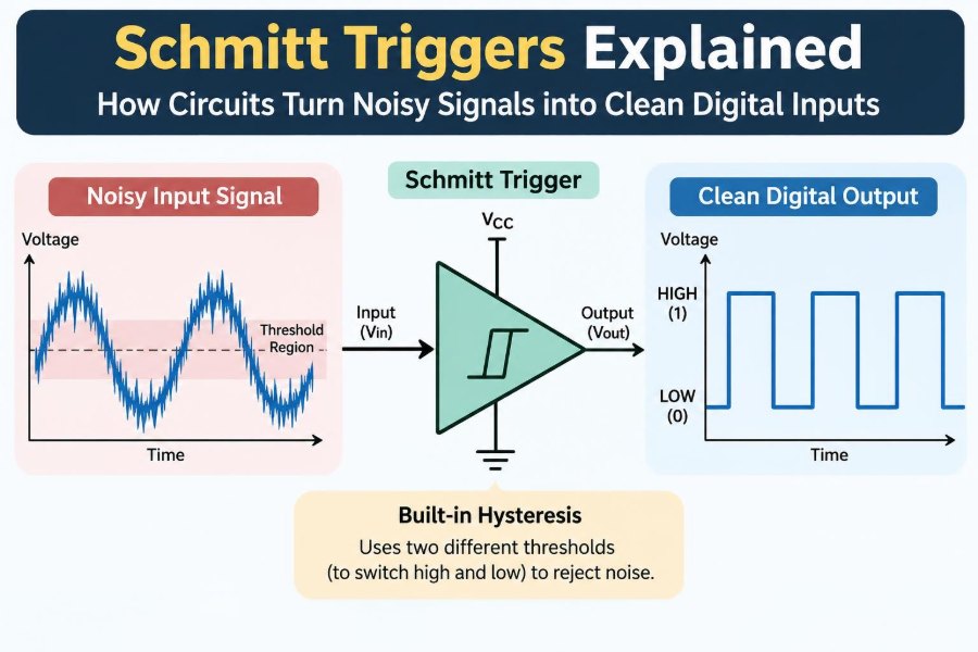

A pushbutton should produce one clean transition: pressed or released. In a real circuit, it may briefly bounce between those states several times. A wire from a sensor may pick up electrical interference. A slowly changing voltage may hover near a logic threshold instead of decisively crossing it.
To a human, these effects are usually invisible. To digital electronics, they can look like several button presses, an unexpected clock pulse, or a stream of rapidly changing logic levels. The result may be intermittent behavior that is difficult to reproduce on the bench.
A Schmitt trigger is a small but powerful circuit idea that addresses this problem. It adds deliberate memory to the decision between LOW and HIGH, allowing a noisy or gradual analog voltage to become a clean digital signal.
The principle appears in logic ICs, microcontrollers, comparators, oscillator circuits, industrial inputs, and many everyday products. Understanding it helps engineers diagnose noisy interfaces and choose input circuits that behave predictably.
🔍 The Basic Job of a Schmitt Trigger
A Schmitt trigger is a threshold circuit with hysteresis. It converts an input voltage into a digital-like output, but it uses one threshold when the input is rising and a different threshold when the input is falling.
An ordinary comparator changes output when its input crosses one reference voltage. A Schmitt trigger instead requires the signal to cross an upper threshold before switching HIGH, then fall below a lower threshold before switching LOW.
The gap between those thresholds prevents small fluctuations near one boundary from repeatedly changing the output.
⚖️ Why One Switching Threshold Can Fail
Consider a standard logic input with a single effective switching point. If a noisy input sits near that point, even a few millivolts of disturbance can move it from one side to the other and back again.
This is especially troublesome when the source changes slowly, such as an RC timing capacitor, a fading light sensor, or a mechanical switch. The input spends longer in the uncertain region, giving noise more opportunities to create false transitions.
A single-threshold input is not inherently defective; it is appropriate when the incoming signal has fast, well-controlled edges. But it has little tolerance for ambiguous analog behavior.
🔁 Hysteresis: The Essential Idea
Hysteresis means the circuit response depends partly on its present state. The voltage required to make the output go HIGH differs from the voltage required to make it go LOW.
Suppose a hypothetical input must rise above 3 V to switch the output HIGH, but must fall below 2 V to return the output LOW. Once the output is HIGH, noise between 2 V and 3 V does not matter. The circuit stays HIGH until the input makes a clear downward move.
This 1 V interval is the hysteresis band. It is a deliberate dead band, not indecision.
📈 The Two Thresholds on a Transfer Curve
A voltage transfer curve plots output voltage against input voltage. For a Schmitt trigger, the curve follows different paths depending on whether the input is increasing or decreasing.
The upper threshold, often written as VTH+, is the rising-input switching point. The lower threshold, VTH−, is the falling-input switching point. Their difference is the hysteresis voltage:
V_HYS = V_TH+ − V_TH−Datasheets may specify typical thresholds, minimum and maximum limits, or thresholds as fractions of supply voltage. Designers must use the guaranteed limits when margins matter.
🧠 Positive Feedback Creates the Memory
The classic Schmitt trigger uses positive feedback. A portion of the output is fed back to the input reference in a way that reinforces the current output state.
When the output is LOW, the reference condition favors staying LOW until the input rises far enough. Once the input crosses the upper threshold, the output moves HIGH. That output change shifts the reference so the input must now fall farther before another transition can occur.
This regenerative action makes switching fast. The feedback is positive around the threshold, even though the overall circuit can be built from an inverting amplifier or comparator.
🗣️ A Useful Doorway Analogy
Imagine a doorway with two signs. To enter, a person must move past the line marked “3.” Once inside, they are not considered outside again until they pass the separate line marked “2.”
Standing between the two lines does not change their status. Likewise, an input voltage inside the hysteresis band does not change the Schmitt trigger output.
The analogy is imperfect because voltages are continuous and circuits switch extremely quickly, but it captures the key point: the return condition is intentionally different from the entry condition.
🌊 Where Input Noise Comes From
Noise is any unwanted voltage variation superimposed on a desired signal. Its source may be inside the circuit, coupled in from the environment, or created by the signal source itself.
- Mechanical contacts bounce as metal surfaces settle after opening or closing.
- Long cables can couple to motors, relays, switching supplies, and radio-frequency sources.
- Ground currents can create voltage differences between supposedly common reference points.
- Sensor outputs can contain ripple, vibration-related variation, or quantization artifacts.
- Slow RC ramps are sensitive because they cross a threshold gradually.
A Schmitt trigger does not remove all noise from the analog waveform. It prevents noise within its hysteresis band from becoming extra digital output edges.
🔘 Debouncing a Mechanical Pushbutton
Button debouncing is the most familiar Schmitt trigger application. When contacts close, they may open and close repeatedly for a short interval. A microcontroller sampling this raw node can interpret the event as multiple presses.
A common hardware approach uses a pull-up or pull-down resistor, an RC network, and a Schmitt-trigger input. The capacitor smooths the rapid contact changes, while the Schmitt trigger turns the resulting gradual voltage ramp into one sharp transition.
Software debouncing can also work, but hardware conditioning is valuable when the signal must be clean before firmware runs or when it drives asynchronous hardware directly.
🐢 Slow Edges Are a Separate Problem
A signal does not need visible noise to cause trouble. A very slow edge can keep a conventional CMOS input in its transition region, where both internal transistor networks may conduct partially.
That can increase supply current and make the output vulnerable to small disturbances. The exact behavior depends on the logic family and device architecture, so datasheet guidance is essential.
A Schmitt-trigger input is designed to accept slower transitions more gracefully. It does not remove all input rise-time requirements in every application, but it is generally the better interface for deliberate ramps and slowly changing sensor voltages.
🔌 Logic Gates with Schmitt-Trigger Inputs
Many logic families offer dedicated Schmitt-trigger buffers, inverters, NAND gates, and other gates. These parts combine a familiar Boolean function with hysteretic input behavior.
A Schmitt inverter is particularly useful because it both cleans up the signal and produces its complement. Two inverters in series restore the original polarity while retaining the noise-cleaning benefit.
Never assume a gate has hysteresis merely because it is a CMOS device. Look for explicit datasheet wording such as “Schmitt-trigger input,” and check the specified threshold characteristics.
⚔️ Schmitt Trigger Versus Comparator
A comparator compares two voltages and produces a high or low output. It may have no hysteresis, built-in hysteresis, or externally added hysteresis. A Schmitt trigger is therefore best understood as a threshold function with hysteresis, not as a completely separate physical category.
| Feature | Basic comparator | Schmitt-trigger function |
|---|---|---|
| Switching boundary | Usually one reference threshold | Separate rising and falling thresholds |
| Noise near threshold | May cause output chatter | Tolerated within hysteresis band |
| Reference flexibility | Often easy to set externally | May be fixed or externally designed |
| Typical use | Precise level comparison | Signal conditioning and clean transitions |
For an adjustable sensor trip point, a comparator with externally designed hysteresis is often a better fit than a fixed-threshold logic gate.
🧮 Designing Hysteresis with a Comparator
An external Schmitt trigger can be built with a comparator and a resistor network that feeds part of the output back to the reference input. The output voltage changes the reference level, creating two trip points.
The resistor values determine how much output movement is fed back. More feedback produces a wider hysteresis band; less feedback produces a narrower one. A bias source or reference voltage places the band at the desired input level.
Actual design must account for output HIGH and LOW voltages, input bias currents, reference tolerance, resistor tolerance, supply range, and the comparator’s common-mode input range. A textbook equation is only the starting point.
🔄 Inverting and Non-Inverting Arrangements
In an inverting Schmitt trigger, a rising input may produce a falling output. In a non-inverting arrangement, a rising input produces a rising output. Both can provide hysteresis.
The choice is often driven by polarity requirements and convenient resistor connections. It also affects which comparator input receives the signal and which receives the feedback-adjusted reference.
When drawing or reviewing a circuit, trace the behavior at both thresholds rather than relying on a remembered schematic. Ask: what happens when the input rises, and what must happen for it to return?
🧪 The 555 Timer as a Familiar Example
The classic 555 timer contains two internal comparator thresholds and a latch. Its trigger and threshold functions demonstrate hysteresis-like behavior through reference levels derived from the supply voltage.
In an astable oscillator, a capacitor repeatedly charges and discharges between those internal levels. The output changes state when the capacitor reaches each boundary, producing a stable repeating cycle.
The 555 is not simply a general-purpose Schmitt buffer, but it is an excellent example of how two thresholds convert a gradual capacitor voltage into decisive switching events.
⏱️ Turning an RC Ramp into a Digital Pulse
Connect a resistor and capacitor so that a capacitor charges toward the supply rail, then feed that capacitor voltage into a Schmitt inverter. The capacitor voltage rises smoothly, but the inverter output remains in one state until the upper threshold is reached.
At that point, the output snaps to the other state. If the capacitor is discharged, the output does not return until the lower threshold is crossed.
This arrangement is used for delay generation, reset shaping, simple oscillators, and pulse stretching. Timing is not highly precise because capacitance, thresholds, leakage, and supply voltage vary, but it is useful where modest timing accuracy is acceptable.
📶 Cleaning Up Sensor Outputs
Many sensors produce analog voltages rather than logic-compatible digital signals. A light-dependent circuit, Hall sensor interface, thermistor divider, or liquid-level probe may drift slowly around a decision point.
Adding hysteresis prevents an output from oscillating when the measured quantity sits near the trip level. For example, a fan controller can turn on at a higher temperature and turn off only after temperature falls somewhat lower.
The separation should reflect real system variation. Too little hysteresis permits chatter; too much can make the system respond later than intended.
🏭 Long Wires and Industrial Inputs
Long wiring runs are antennas as well as conductors. Fast switching loads, relay coils, and variable-speed drives can couple transient energy into nearby signal cables.
A Schmitt-trigger stage can improve the immunity of a digital interface, but it is not a substitute for sound wiring practice. Shielding, twisted pairs, correct grounding, appropriate cable routing, surge protection, and input filtering may all be necessary.
For equipment connected beyond a local circuit board, also consider voltage range, isolation requirements, electrostatic discharge, and fault conditions. Logic-level hysteresis alone cannot make an unsafe or overstressed input robust.
🔋 Supply Voltage Changes the Thresholds
In many CMOS Schmitt-trigger devices, switching thresholds move with supply voltage. A threshold may be specified as a proportion of VCC rather than as one fixed voltage.
This matters when the source voltage is fixed but the logic supply varies. A sensor output that reliably crosses a threshold at one supply voltage may have reduced margin at another.
Read threshold specifications alongside the supply-voltage range. For a precise fixed trip point, use a stable reference and a suitable comparator rather than assuming a logic-gate threshold is exact.
📏 Choosing the Right Hysteresis Width
The hysteresis band should exceed the expected combination of noise, ripple, and ordinary signal uncertainty near the switching point. It should not be so wide that the circuit ignores a meaningful input change.
Suppose a sensor normally fluctuates by a small amount because of vibration. The hysteresis should be wider than that normal fluctuation, with margin for component variation. Then the sensor must make a genuine directional change before the output changes.
There is no universal “correct” width. The best value depends on noise amplitude, source slope, acceptable switching delay, required accuracy, and worst-case supply and temperature conditions.
🧩 Input Source Impedance Matters
A high-impedance source can be easily disturbed by leakage currents, capacitive coupling, and board contamination. Even when a Schmitt trigger provides hysteresis, the input node may be slow, noisy, or vulnerable to electrostatic discharge.
Use a suitable pull-up or pull-down resistor to define the state of switch inputs and open-drain outputs. Choose its value based on current consumption, edge speed, cable capacitance, leakage, and the input’s electrical requirements.
Do not leave CMOS inputs floating. A floating input can assume unpredictable voltages and may switch repeatedly regardless of whether the device has Schmitt-trigger characteristics.
🛡️ Filtering and Hysteresis Solve Different Problems
An RC filter reduces high-frequency content and smooths short disturbances. Hysteresis prevents output state changes while the input remains inside a voltage band. These tools complement each other, but they are not interchangeable.
A brief high-amplitude transient may cross both thresholds even if hysteresis is present. Conversely, an RC filter alone can create slow edges that are troublesome for a non-Schmitt input.
A practical front end often uses both: filtering to reduce unwanted disturbances and a Schmitt trigger to make the final digital decision cleanly.
⚡ Fast Transients Can Still Win
Hysteresis is not a guarantee against every false trigger. A sufficiently large or fast interference pulse can cross the active threshold, and a severe transient may exceed the input’s absolute maximum ratings before logic behavior is relevant.
Protect exposed inputs with an architecture suited to the environment: series resistance, clamps selected for the system voltage, filtering, shielding, and isolation where required. Verify that any protective component does not create an unacceptable leakage path or excessive source impedance.
Think of hysteresis as a noise margin around a decision point, not as a complete electromagnetic compatibility strategy.
🧷 Schmitt Triggers Are Not Metastability Cures
When an asynchronous signal is sampled by a clocked digital system, it can violate setup or hold time and lead to metastability: a flip-flop temporarily takes an indeterminate time to resolve.
A Schmitt trigger can clean a slow or noisy edge before it reaches the clocked domain, which is helpful. However, it cannot guarantee that an asynchronous transition will avoid the sampling aperture of a flip-flop.
Use synchronizer flip-flops, suitable clock-domain crossing methods, and protocol-aware design when signals pass between unrelated timing domains. Signal conditioning and synchronization address different failure mechanisms.
🖥️ Microcontroller Pins Need Datasheet Checks
Some microcontroller GPIO pins include Schmitt-trigger input buffers; others may not, or may behave differently in analog, wake-up, high-speed, or reset-related modes. Pin behavior can also differ across families and supply ranges.
Check the electrical characteristics, input hysteresis specification, enabled peripheral mode, and recommended input transition rates. An internal pull resistor may be convenient but is often loosely specified and may not suit a cable or timing network.
For a safety-critical, high-noise, or externally accessible signal, an external conditioning circuit is often easier to analyze and protect than relying solely on undocumented assumptions about a GPIO input.
🧱 Board Layout Can Preserve or Defeat the Design
A carefully chosen Schmitt trigger cannot compensate for poor physical layout. High-current switching loops, fast clock traces, and relay-drive paths can inject noise into a sensitive threshold node through shared impedance or capacitive coupling.
Keep the analog input path short where possible. Place the RC components and protective parts close to the receiving input, provide a sensible return path, and separate noisy power switching areas from low-level sensing nodes.
Ground is not magically identical everywhere on a board. The voltage drop along a return path can become part of the signal seen by the input circuit.
🔬 Measuring a Noisy Threshold Problem
An oscilloscope is usually the most direct diagnostic tool. Probe the raw input and conditioned output, ideally with attention to probe grounding and bandwidth so the measurement does not exaggerate or hide the problem.
Look for slow crossings, bursts of narrow pulses, bounce, ripple near the threshold, or output chatter. A logic analyzer may show extra digital events, but it cannot reveal why the analog node crossed the boundary.
Test under realistic conditions: cables connected, loads switching, supply voltage at its expected limits, and temperature or vibration present when relevant. Intermittent input problems often disappear in an overly quiet test setup.
🚫 Common Design Mistakes
- Assuming every logic input is Schmitt-triggered: verify the exact part and pin in the datasheet.
- Using only a capacitor for a button: include a defined DC path and consider the input’s switching behavior.
- Making hysteresis enormous: this may eliminate chatter while introducing unacceptable delay or measurement error.
- Ignoring threshold tolerance: typical values are not sufficient for worst-case designs.
- Connecting external signals directly to a GPIO: consider voltage levels, fault current, ESD, and cable-borne transients.
- Trying to solve layout noise only in software: firmware cannot recover an edge that has already triggered hardware incorrectly.
🧰 A Practical Design Workflow
- Define the source: switch, sensor, cable, RC ramp, or another digital device.
- Identify normal voltage range, edge rate, noise amplitude, and possible fault voltages.
- Choose whether a fixed Schmitt gate or an adjustable comparator circuit fits the required threshold.
- Set hysteresis wider than expected nuisance variation while checking required response points.
- Add filtering and protection appropriate to the physical environment.
- Check worst-case thresholds, supply range, temperature behavior, and component tolerances.
- Measure the completed circuit under realistic switching and interference conditions.
This sequence prevents the common mistake of selecting a convenient IC before defining what the input must survive and recognize.
🧭 When Not to Use a Schmitt Trigger Alone
Some tasks need more than a simple two-state threshold. Precision measurement may require an analog-to-digital converter and calibrated processing. Very short events may require a faster comparator, a one-shot circuit, or specialized signal conditioning.
For signals with severe common-mode noise, differential receivers may be more appropriate. For safety interlocks, redundancy, diagnostics, and fail-safe behavior may be required beyond a single threshold stage.
The Schmitt trigger is a foundational building block, not a universal front-end solution. Its strength is making a clear decision when the signal meaningfully crosses a well-chosen boundary.
✅ The Core Principle: Clean Decisions Need Margin
A Schmitt trigger transforms uncertain threshold crossings into stable digital transitions by using two distinct switching levels. Positive feedback creates a memory effect: after a transition, the signal must move decisively in the opposite direction to reverse it.
That simple behavior makes it valuable for buttons, sensors, slow ramps, cable inputs, and oscillator circuits. Yet good results still depend on correct threshold selection, supply and tolerance analysis, protection, layout, and appropriate handling of asynchronous digital signals.
The most useful design question is not merely “Does this input cross the threshold?” Ask whether it crosses with enough margin, at the right speed, and in the presence of the noise the real system will encounter.
Schmitt triggers do not make a noisy signal perfect; they make digital decisions resistant to small uncertainty around a carefully chosen boundary. That is why such a modest circuit feature has an outsized role in reliable electronics. 🔌📈🛠️