
A board that will not power up creates a familiar kind of uncertainty. The status LED may remain dark, a fuse may open immediately, or the device may appear to start and then reset whenever it is asked to do real work.
These symptoms often tempt a technician to replace the most visibly damaged component. Sometimes that works. More often, power faults are interconnected: a shorted load can make a regulator look bad, a missing enable signal can mimic a failed regulator, and a poor ground connection can produce misleading voltage readings.
Effective fault tracing is therefore less about guessing and more about following energy through the circuit. Start at the input, establish what condition the board is in, and verify each stage before moving downstream.
This method applies to many low-voltage electronic boards, from consumer devices to embedded controllers. It does not make every repair simple, but it makes the investigation controlled, repeatable, and much safer.
🔍 Start with the Power Path, Not the Symptom
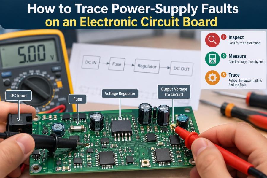
A power supply is a chain, not one component. Typical stages include an input connector, protection components, a fuse, a switch or controller, rectification or conversion circuitry, filters, regulators, and the loads being supplied.
Draw or annotate that chain before probing. The central question is simple: where does the expected voltage first disappear, become incorrect, or collapse under load? Everything before that point is a likely source of the fault; everything after it may be an affected load.
⚠️ Set Safe Boundaries Before Connecting Power
Power-supply work can involve stored energy, high current, and—in equipment connected to the mains—hazardous voltages. Do not troubleshoot live mains circuitry unless you have appropriate training, tools, isolation practices, and an understanding of the specific equipment.
Even disconnected boards can retain charge in large capacitors. Verify voltage with a meter before handling conductors, and discharge capacitors only by a method suitable for the circuit. Never short a charged capacitor directly with a screwdriver or wire.
For low-voltage board testing, remove rings and watches, use insulated probes, secure the board on a nonconductive surface, and avoid probing with both hands around energized circuitry.
🧰 Gather the Tools That Actually Help
A digital multimeter is the basic instrument. It measures resistance, continuity, diode voltage drop, DC voltage, and often current. A bench power supply with adjustable voltage and current limiting adds a major diagnostic advantage because it can energize a suspect board without allowing uncontrolled current.
Useful supporting tools include:
- Fine multimeter probes, clips, and probe hooks
- A magnifier or microscope for solder joints and small packages
- Thermal camera, infrared viewer, or isopropyl alcohol for locating hot parts
- Oscilloscope for ripple, startup, and switching-node checks
- Board schematic, layout, or a known-good board when available
An oscilloscope is valuable, but it is not the first tool for every failure. A systematic meter-based check often identifies a short, open fuse, absent input, or disabled regulator quickly.
📄 Read the Schematic as a Map of Intent
A schematic tells you what the designer expected to happen. Identify each named rail, such as VIN, 12 V, 5 V, 3V3, VCORE, or VREF, and note which component generates it and which circuits consume it.
Follow net labels across pages. A 3.3 V rail may not originate near the microcontroller; it may travel through a ferrite bead, load switch, or jumper from a regulator elsewhere on the board.
If no schematic exists, work from component markings, copper traces, and datasheets. Build a simple handwritten map: input voltage, protection stage, major regulators, and accessible test points.
👀 Inspect Before You Measure
With power removed, inspect both sides of the board under strong light. Look for cracked connectors, lifted pads, burnt resistors, damaged inductors, corroded areas, solder bridges, and discolored laminate.
Electrolytic capacitors with domed tops or leaked electrolyte deserve attention, but appearance alone is not proof of failure. Conversely, multilayer ceramic capacitors frequently fail short circuit while looking completely normal.
Also inspect the mechanical context. A board that failed after a drop may have fractured solder joints. A board from a damp environment may have conductive contamination or corrosion around fine-pitch devices.
🔌 Confirm the External Source First
Do not assume the adapter, battery, cable, or upstream supply is healthy because its label states a voltage. Measure it. Check connector polarity and verify that the source maintains its rated voltage when connected to an appropriate load.
A damaged cable can show correct voltage with no load and fail when current is drawn. Similarly, some adapters enter protection mode when they see a shorted board, making the output appear absent only after connection.
For batteries, measure terminal voltage and inspect connectors, protection boards, and fuses. A battery-management circuit may intentionally disconnect a pack under undervoltage, overcurrent, or temperature conditions.
🧭 Identify Ground and Establish a Measurement Reference
Voltage is always measured between two points. On most low-voltage boards, the negative input terminal, large ground plane, connector shell, or marked GND pad provides a reference point.
Clip the meter’s black lead to a confirmed ground point, then use the red probe to trace the positive path. This reduces mistakes and makes measurements comparable from one test point to the next.
Be careful with isolated power supplies and primary-side mains circuits. Their “ground” may not be safe earth ground, and connecting an earthed oscilloscope probe in the wrong place can create a destructive short circuit.
🛡️ Check Fuses, PTCs, and Protection Components
With power removed, test ordinary fuses for continuity. A good fuse should have very low resistance; an open reading means it has operated or failed. Replacing it without finding the cause can sacrifice the replacement immediately.
Also examine resettable fuses, reverse-polarity MOSFETs, series diodes, transient-voltage suppressors, and input common-mode filters. A shorted transient suppressor diode, for example, can clamp the input rail so hard that the whole board appears dead.
Measure voltage on both sides of a protective component while powered, where safe. A substantial unexpected voltage drop across a fuse, diode, switch, or connector reveals that it is blocking the path or carrying excessive current.
📏 Use Resistance-to-Ground as an Early Clue
Before applying power to a suspect rail, measure its resistance to ground with the board disconnected. Very low resistance can indicate a short, but the result needs interpretation.
High-current rails such as processor cores can naturally have low resistance because they feed many semiconductor junctions in parallel. A rail reading of a few ohms is not automatically defective. Compare with a known-good board, schematic expectations, or other identical rails when possible.
A reading near zero that is stable, especially on a general 5 V or 12 V rail, is more suspicious. Note the measured value instead of relying on a continuity beeper; many meters beep at resistances that are normal for electronics.
🔋 Use Diode Mode to Spot Semiconductor Clamps
Diode mode applies a small test current and reports the voltage developed across the probes. It is often more informative than continuity mode when checking input rails, MOSFETs, diodes, and IC supply pins.
Measure from the rail to ground in both polarities and record the values. A shorted diode or MOSFET may read near zero in both directions. A healthy silicon diode usually conducts in one direction and blocks in the other, although in-circuit paths can complicate the result.
Diode-mode readings are comparative evidence, not a universal pass/fail number. Parallel components and internal ESD protection diodes can produce valid readings that differ from a simple standalone diode.
🧪 Power a Suspect Board with Current Limiting
When the normal source is questionable or the board may be shorted, use a bench supply set to the board’s correct input voltage. Start with a conservative current limit, then increase only when the board’s normal operating current and fault condition justify it.
If the supply immediately enters constant-current mode and the voltage falls well below the setting, the board is drawing more current than allowed. That strongly suggests a short or severe overload on the powered path.
Current limiting is not a cure. It is a controlled way to observe a fault while reducing the chance of burnt traces, damaged adapters, or repeated fuse failures.
🌡️ Locate a Short by Looking for Heat
A shorted component converts injected electrical power into heat. With a low, controlled voltage applied to the affected rail, the fault location may become warmer than its surroundings.
A thermal camera is the clearest option. Alternatives include observing alcohol evaporate first from the warm component or cautiously using a temperature-sensitive method designed for electronics work. Avoid touching energized boards with bare fingers.
Use only enough voltage and current to create a detectable temperature difference. Raising the injection voltage beyond what the rail normally sees can damage downstream ICs, especially low-voltage core circuits.
🔁 Separate the Source from the Load
A regulator output that reads 0 V does not prove the regulator is faulty. Its input may be missing, its enable pin may be low, its feedback network may be damaged, or a downstream short may be forcing it into current limit.
Where the design permits it, isolate sections by removing a ferrite bead, zero-ohm link, inductor, fuse, or load switch. Then recheck resistance and voltage on both sides. The side retaining the low resistance contains the likely short.
This technique must be planned carefully. Do not remove random parts from densely coupled circuits, and do not force an isolated rail from an external supply unless you understand every connected signal path.
⚙️ Understand Linear Regulator Failure Modes
A linear regulator drops excess voltage as heat. Its basic checks are input voltage, output voltage, ground connection, enable state, and output condition. A device specified for 3.3 V cannot produce that output from a 3.0 V input, allowing for its required dropout margin.
If input is correct and enable is asserted but output is low, disconnect or isolate the load before condemning the regulator. A shorted output capacitor or IC may cause a good regulator to fold back or shut down.
Some regulators require a specific output capacitor value and effective resistance for stability. Installing an unsuitable replacement capacitor can cause oscillation even though a meter reports an apparently correct average voltage.
🔄 Understand Switching Regulator Clues
Buck, boost, and buck-boost regulators transfer energy through a rapidly switched inductor. Their output can fail because of a defective controller, MOSFET, diode or synchronous switch, inductor, feedback network, bootstrap capacitor, or load.
A switch-mode regulator may chirp, pulse, or periodically attempt startup when it detects overcurrent. A meter can average these pulses into a confusing low value. An oscilloscope can reveal whether switching exists, but probe the switching node only with appropriate bandwidth, grounding, and safety awareness.
Check the simple conditions first: correct input, no output short, valid enable, and intact inductor path. Inductors can crack internally or develop poor solder joints, leaving a regulator active but unable to deliver energy to its output.
📌 Check Enable, Power-Good, and Sequencing Signals
Many power rails are intentionally off until an enable pin rises above a threshold. A missing enable can originate from a power button circuit, supervisor IC, microcontroller, battery-management controller, or another rail’s power-good output.
Measure the enable pin against the regulator’s datasheet logic thresholds. Do not assume that a pin labeled EN must be high; some controllers use active-low shutdown signals or have internal pull resistors.
Complex digital boards may require rails in a particular order. If an upstream standby rail is missing, downstream regulators may all look defective when they are simply never instructed to start.
📈 Distinguish DC Voltage from Power Quality
A meter reading of 5.0 V is useful but incomplete. The rail may still contain excessive ripple, switching spikes, or brief dropouts that reset digital logic and corrupt analog measurements.
An oscilloscope shows the time behavior that a meter averages away. Check ripple at the load as well as at the regulator, using a short ground connection on the probe to avoid picking up artificial noise.
Large ripple may point to dried or disconnected capacitors, overload, poor regulator control, or a bad connection. The acceptable ripple depends on the rail and application, so use the component datasheet or system requirements rather than a generic limit.
🧲 Do Not Overlook Connectors, Vias, and Solder Joints
Intermittent power faults often occur in passive mechanical features rather than active components. A cracked barrel-jack pin, oxidized battery contact, broken via, or fractured regulator pad can create voltage loss only when the board flexes or draws current.
Measure voltage on both ends of suspicious interconnects while the board is powered. Gently manipulate the connector or board only when it can be done safely, and watch for changes in voltage or current.
Reflowing every joint “just in case” is risky. It can hide evidence, lift pads, and create bridges. Inspect, measure, and repair a specific suspected defect.
🧩 Treat Capacitors as Circuit Participants
Capacitors filter ripple, supply short bursts of current, set controller timing, and stabilize regulator feedback loops. Their failures include short circuit, open circuit, high equivalent series resistance, leakage, and loss of capacitance.
A shorted ceramic capacitor is common on dense low-voltage rails and is usually found through low-resistance testing and controlled current injection. A high-resistance or dried electrolytic capacitor may instead cause ripple, startup cycling, or instability.
In-circuit capacitance measurements can be misleading because parallel capacitors affect the result. An ESR meter or temporary substitution with a suitable known-good part can help, provided voltage rating, polarity, capacitance, and intended regulator stability requirements are respected.
🧯 Recognize Overcurrent and Thermal Shutdown
Some boards appear to turn on briefly, then die, then try again. This repeating pattern can be a regulator’s protection response rather than a software problem. Common triggers include output shorts, stalled motors, wrong loads, and overheated power devices.
Observe supply current during startup. A sharp rise followed by a drop, repeating at a regular interval, is a useful signature of hiccup-mode protection. The exact behavior varies by controller.
Find out what changed before the failure. A new peripheral, a pinched cable, or a mechanically jammed load may be the actual overcurrent source.
🧠 Account for Digital Loads and Hidden Short Paths
Microcontrollers, memory, displays, sensors, and communication ICs can create complex paths between rails through internal protection structures. Back-powering occurs when a signal is driven into an unpowered IC, allowing current to flow through an internal clamp diode to its supply rail.
This can make a rail sit at an unexpected partial voltage and confuse troubleshooting. Disconnect external cables and modules when practical, then see whether the abnormal voltage or current draw changes.
Never assume a low rail voltage proves that its own regulator is active. It may be receiving leakage or backfeed from another powered interface.
🧷 Measure Voltage Drop Under Real Load
An open or resistive connection may look fine with no load. Under current, even a small unwanted resistance causes a voltage drop according to the relationship V = I × R.
For example, a connector contact or cracked trace with only a fraction of an ohm of resistance can lose a meaningful portion of a low-voltage rail when several amperes flow. Measure across the suspected connection while the circuit is operating; a noticeable drop identifies where power is being wasted.
This approach is especially useful for battery contacts, fuses, cables, MOSFET switches, shunt resistors, and ground returns.
📝 Keep a Measurement Log Instead of Trusting Memory
Record each rail’s expected voltage, measured voltage, resistance to ground, and operating condition. Note whether measurements were made with the normal adapter, bench supply, no external loads, or a connected subsystem.
| Test point | Expected condition | Observed result | What it suggests |
|---|---|---|---|
| Input after fuse | Input voltage present | 0 V | Open fuse, connector, or upstream protection issue |
| Regulator input | Within device range | Correct | Trace enable and output next |
| Regulator output | Specified rail voltage | Low, supply current limited | Possible overload or output short |
| Downstream rail after bead | Similar to source rail | Absent | Open bead, link, or load switch |
A log prevents circular testing and helps another technician understand the diagnosis. It also makes intermittent faults easier to correlate with temperature, movement, or load.
🧪 Change Only One Variable at a Time
Replace one suspect part, reconnect one module, or alter one supply setting per test. If several changes are made together, a successful result does not reveal which change solved the problem, and a new failure may be harder to isolate.
After a component replacement, repeat the relevant unpowered resistance checks before applying full power. Confirm part orientation, pinout, voltage rating, and package compatibility; parts with similar markings are not necessarily electrically interchangeable.
For a hypothetical 5 V board with a shorted input suppressor, replacing both the suppressor and fuse together may restore operation, but testing the rail before fitting the fuse would better confirm that the short was removed.
🚫 Avoid Common Fault-Tracing Traps
Several habits slow diagnosis or create additional damage:
- Replacing a blown fuse without checking for a downstream short
- Using continuity beeps as proof that a rail is shorted
- Injecting voltage into a rail without knowing its normal voltage and connected ICs
- Probing adjacent fine-pitch pins with oversized probe tips
- Declaring a regulator bad without checking input, enable, load, and feedback
- Using a long oscilloscope ground lead that displays noise the circuit did not create
- Testing a live mains-derived primary circuit with unsuitable grounded equipment
The recurring correction is to measure a defined condition, form a limited hypothesis, and test that hypothesis with the least invasive method.
🔧 Verify the Repair at Idle and at Load
A repaired board should do more than illuminate an LED. Check that all principal rails reach their intended values, startup is repeatable, and input current is plausible for the device’s operating state.
Then test the condition that originally exposed the failure: charging, motor operation, display brightness, communications activity, or processor load. Watch for excess heating, rail droop, resets, or noise that returns after several minutes.
If a protective part failed, determine whether it was responding to an external event or an internal defect. A repair that restores function but leaves the original stress source unresolved may not last.
🗺️ Build a Repeatable Diagnostic Sequence
A reliable sequence reduces guesswork:
- Inspect the board and verify the external source.
- With power removed, check input resistance and obvious protective components.
- Apply controlled power with appropriate current limiting.
- Trace voltage from input through each power-path stage.
- Check regulator input, enable, output, and load condition.
- Isolate a rail when evidence points to a downstream fault.
- Assess ripple, heating, and voltage drop where basic DC checks are inconclusive.
- Repair, then validate under the actual operating load.
The order matters because it moves from broad, low-risk observations to focused intervention. It also avoids spending time analyzing downstream circuits that never received valid power.
✅ The Core Principle: Follow Energy and Evidence
Power-supply troubleshooting becomes manageable when each reading answers a specific question. Is power reaching this point? Is this device being enabled? Is the rail overloaded? Is a connection dropping voltage only under current?
The best diagnosis is usually not the fastest component swap. It is the explanation that accounts for the observed voltages, current behavior, protection response, and physical condition of the board with the fewest assumptions.
Respect the limits of in-circuit measurements, especially on complex boards. When readings are ambiguous, compare against documentation or a known-good unit, isolate the relevant section, and test again rather than forcing a conclusion.
Trace power stage by stage, control the energy you apply, and let measurements—not appearances—identify the real fault. That approach protects the board, improves repair confidence, and turns a “dead” circuit into a solvable electrical path. ⚡🔧🧰