
An electric vehicle is climbing a long hill on a hot afternoon. The driver asks for strong acceleration, the battery is delivering high current, and temperatures inside the pack are rising even though nothing looks unusual from the cabin.
Later that night, the same vehicle is plugged into a charger. One cell reaches its charge limit slightly before its neighbours. Without careful supervision, that small difference could grow with every charging cycle.
This is why an EV battery is not simply a large collection of lithium-ion cells connected to a motor. It is an electrochemical energy system that needs continuous observation, calculation, and control.
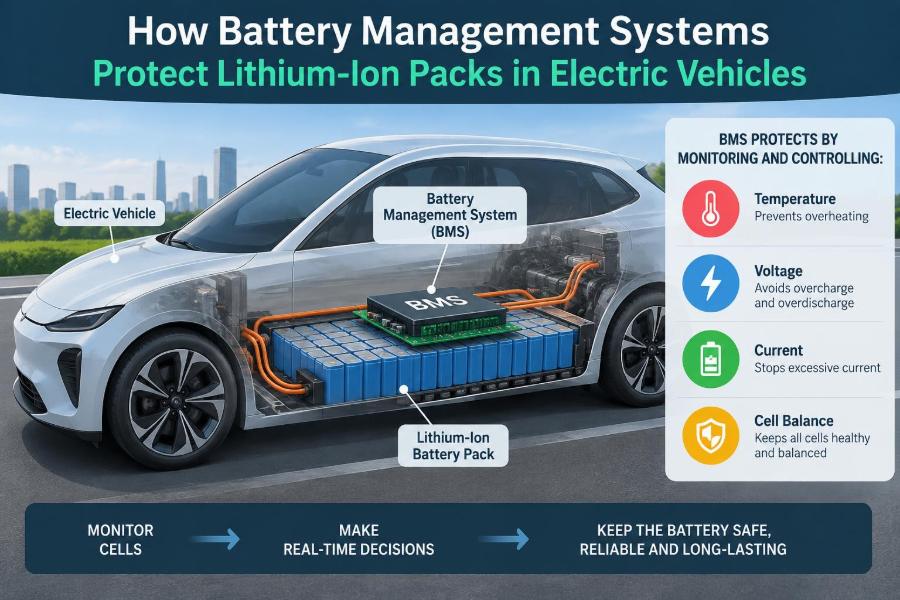
The battery management system, or BMS, is the electronic system that performs this work. It helps the pack deliver useful power while keeping each cell inside safe electrical and thermal operating limits. 🔋
🔋 1. What a Battery Management System Is
A BMS is a combination of sensors, electronics, embedded software, communication networks, and safety logic. Its task is to monitor the battery and make decisions that protect it.
In an EV, the BMS measures cell voltages, pack current, and temperatures. It uses those measurements to estimate battery condition, command charging and discharging limits, operate contactors, and communicate with other vehicle controllers.
It is not usually the device that directly cools a battery or drives the motor. Instead, it coordinates with the charging system, thermal-management system, inverter, and vehicle control unit.
🧩 2. Why a Pack Cannot Be Treated as One Giant Cell
EV packs contain many individual cells arranged in series and parallel. Series connections raise voltage, while parallel connections increase energy capacity and current capability.
No two cells remain perfectly identical throughout their life. Small differences in manufacturing, temperature exposure, internal resistance, and ageing mean that cells gradually behave differently.
A single weak cell can determine the safe limit for an entire series string. The BMS therefore protects the pack by paying attention to the smallest monitored unit, often called a cell or cell group.
⚡ 3. Series Strings Create a Voltage Challenge
In a series string, the same current flows through every cell. However, each cell can have a different voltage and state of charge.
During charging, a cell with less usable capacity may reach its upper voltage limit first. During discharge, that same cell may reach its lower limit first.
The BMS cannot safely rely only on total pack voltage. A normal-looking pack voltage can hide one cell that is already approaching an unsafe condition.
🌡️ 4. Temperature Is as Important as Voltage
Lithium-ion cells are strongly affected by temperature. Their available power, charging acceptance, resistance, and rate of ageing all change as temperature changes.
Very cold cells may not accept charging current safely at the same rate as cells near room temperature. Very hot cells can age faster, and high temperatures can make abnormal events more severe.
For this reason, the BMS monitors temperatures at selected locations and works with heating or cooling equipment to keep the pack in an appropriate operating range.
📏 5. Measuring Individual Cell Voltage
Cell-voltage measurement is one of the BMS’s most important jobs. Dedicated monitoring integrated circuits often measure multiple series-connected cells with high resolution and diagnostic features.
The BMS compares each reading with calibrated thresholds and with the rest of the string. It can identify an over-voltage condition during charging or an under-voltage condition during discharge.
Measurement accuracy matters because the difference between a conservative operating limit and an unwanted shutdown can be small. Engineers must also account for noise, wiring resistance, drift, and sensor faults.
🔌 6. Measuring Pack Current
Current tells the BMS whether energy is entering or leaving the pack and how quickly. The system may use a shunt resistor, Hall-effect sensor, fluxgate sensor, or another current-sensing method.
Current measurement supports several decisions: calculating consumed charge, limiting acceleration power, setting regenerative-braking acceptance, and detecting unexpected current flow.
Both direction and magnitude matter. Charging and discharging may have different limits, especially when temperature or state of charge is near an extreme.
🧊 7. Monitoring Temperature Across the Pack
Temperature sensors are placed near cells, busbars, coolant paths, and sometimes key electronics. A few measurements cannot describe every point inside a large pack, so sensor placement is a careful engineering decision.
The BMS looks for absolute temperature limits and for unusual temperature differences. A local hot spot or a rapidly rising reading can be more informative than the pack-average temperature.
Temperature data also helps the system determine how much charging or propulsion power can be allowed at that moment.
🧠 8. Estimating State of Charge
State of charge, commonly written as SOC, estimates how much usable charge remains. Drivers see it as a battery percentage, but the internal estimation problem is more complicated than a fuel gauge.
A BMS commonly combines current integration, called coulomb counting, with voltage behaviour, temperature data, battery models, and correction routines. Current integration can accumulate error, while voltage alone is not always a reliable instant indicator of charge.
A good SOC estimate supports accurate range information and prevents cells from being pushed beyond their intended charge or discharge limits.
📉 9. Estimating State of Health
State of health, or SOH, describes how the battery has changed with age. It can include remaining capacity, increasing internal resistance, power capability, and other indicators of degradation.
SOH is estimated rather than measured by one simple sensor. The BMS learns from charge throughput, voltage response, temperature history, rest periods, and controlled operating data.
As the pack ages, the BMS can adjust available energy and power estimates so that vehicle behaviour remains safe and predictable.
🔭 10. Predicting State of Power
State of power answers a practical question: how much charge or discharge power can the battery safely provide right now? The answer changes continuously.
A warm, moderately charged pack may support substantial power. A cold pack near empty charge may need much stricter limits, even if its nominal capacity is unchanged.
The BMS sends these limits to the vehicle so the inverter, charger, and regenerative-braking controller can stay within battery capability.
🚧 11. Voltage Limits Prevent Electrochemical Damage
Every cell chemistry and cell design has a specified voltage window. Charging above the upper limit or discharging below the lower limit can cause permanent damage and may create safety concerns.
When a limit is approached, the BMS usually reduces permitted current before opening the main circuit. This controlled derating avoids abrupt interruption whenever normal operating conditions allow it.
If a voltage threshold is crossed or a fault is severe, the system can command charging or discharging to stop.
🛑 12. Current Limits Protect Cells and Conductors
High current creates heat in cells, busbars, connectors, fuses, and contactors. It also increases voltage drop caused by internal resistance.
The BMS calculates allowable current based on cell voltage, temperature, SOC, estimated resistance, and fault status. It may limit power during hard acceleration, towing, fast charging, or regenerative braking.
These limits are not signs that the battery has failed. They are active protection decisions made to keep operation within a safe envelope.
♨️ 13. Thermal Management Works With the BMS
The thermal system moves heat using air, liquid coolant, refrigerant-based systems, heaters, pumps, valves, and heat exchangers, depending on the vehicle design. The BMS supplies the information needed to control it intelligently.
For example, it may request cooling when cell temperatures rise during fast charging. It may request heating before charging a cold battery.
Thermal control also aims for temperature uniformity. Cells at very different temperatures tend to age and perform differently, making balancing and estimation more difficult.
⚖️ 14. Cell Balancing Keeps Series Cells Aligned
Cell balancing reduces differences in charge level among cells in a series string. Without it, the highest-charged cell reaches the upper limit early, while the lowest-charged cell reaches the lower limit early.
Balancing does not make an aged or damaged cell new again. Its role is to prevent ordinary small mismatches from unnecessarily reducing pack usable capacity.
Two common approaches
- Passive balancing removes a small amount of energy from higher-voltage cells as heat through resistors.
- Active balancing transfers energy between cells or groups using power-electronic circuits, with greater circuit complexity.
Many systems balance primarily near the end of charging, when differences in cell charge state are easier to observe.
🔗 15. Contactors Connect and Isolate High Voltage
Large EV packs use high-voltage contactors, which are electrically controlled switches designed for the pack’s voltage and current. The BMS commands these contactors during startup, shutdown, charging, and fault handling.
Opening the contactors can isolate the traction battery from the rest of the high-voltage system. This is a central protective action when the BMS detects a serious electrical or thermal problem.
Because contactors are mechanical devices, the BMS may also monitor their expected response and look for evidence of welded or failed contacts.
🪫 16. Precharge Prevents Inrush Current
Before the main contactors close, the inverter and other vehicle electronics may contain large capacitors at low voltage. Directly connecting the battery could cause a very high inrush current.
A precharge circuit connects the pack through a resistor for a short controlled interval. This gradually raises the downstream capacitor voltage before the main positive contactor closes.
The BMS checks whether voltage rises as expected. If it does not, the system can avoid completing the high-voltage connection.
🧯 17. Fault Detection Needs Layers
A robust BMS does not depend on one sensor or one threshold. It uses layered diagnostics, plausibility checks, timers, redundant measurements where needed, and fault classifications.
Examples include a voltage reading that is implausible compared with adjacent cells, a current sensor disagreement, an open temperature-sensor circuit, or a contactor that does not behave as commanded.
Responses can range from recording a diagnostic event to reducing power, disabling charging, or isolating the pack. The response should match the severity and confidence of the fault.
🚨 18. Detecting Insulation and Isolation Faults
The high-voltage battery is electrically isolated from the vehicle chassis in normal operation. An insulation fault can create an unwanted path between the high-voltage system and the chassis.
Isolation monitoring helps identify this condition. The BMS or a dedicated device can then warn the vehicle, restrict operation, or disconnect the battery according to the system’s safety strategy.
This protection is especially important because moisture, damaged insulation, contamination, and crash damage can change electrical isolation.
🧨 19. Managing Thermal-Runaway Risk
Thermal runaway is a self-heating failure process that can occur when a cell is severely abused, internally damaged, or exposed to excessive heat. It is a hazardous event requiring prevention, detection, and mitigation at multiple levels.
The BMS helps by preventing overcharge, excessive discharge current, and operation outside temperature limits. It can also detect abnormal temperature rise and initiate protective actions early.
However, a BMS is only one layer of pack safety. Cell selection, mechanical design, thermal barriers, venting paths, fusing, crash structures, and emergency procedures all matter.
📡 20. Communication Lets the Vehicle Act on Battery Data
The BMS exchanges information with other electronic control units, commonly over an automotive communication network. It may report SOC, SOH, temperature, available power, fault state, and charging permission.
The charger needs to know what voltage and current the battery can accept. The powertrain controller needs to know how much propulsion and regeneration the battery can support.
Clear communication ensures that the vehicle acts on the battery’s real-time condition rather than assuming fixed limits.
🔒 21. Functional Safety Shapes BMS Design
Failures in a battery system can have serious consequences, so BMS hardware and software are developed with systematic safety thinking. Designers identify hazards, analyze possible faults, and define safe responses.
Safety mechanisms may include watchdog timers, independent voltage checks, redundant sensing paths, diagnostic coverage, controlled shutdown procedures, and fault memory.
The goal is not to claim that faults never occur. It is to detect credible faults, limit their effects, and move the system toward a safe state.
🖥️ 22. Software Turns Measurements Into Decisions
Raw sensor values are not enough. Embedded software filters noisy signals, compensates for temperature, estimates internal states, evaluates fault logic, and sends commands at appropriate rates.
Software must distinguish a brief measurement spike from a sustained dangerous condition. It must also behave predictably when data is missing, inconsistent, or outside expected ranges.
Calibration is important too. Thresholds, model parameters, and derating curves must match the cells, pack design, cooling system, and intended vehicle use.
🧪 23. Validation Includes More Than Normal Driving
BMS development involves testing under normal use and under difficult conditions. Engineers evaluate hot and cold operation, charging behaviour, sensor errors, communication losses, power interruptions, and abnormal electrical events.
Hardware-in-the-loop systems can simulate battery and vehicle signals so that control logic can be tested before every situation is attempted in a physical vehicle. Cell and pack testing then checks whether models and limits reflect real electrochemical behaviour.
Testing must include transitions, not only steady states. Starting, stopping, plugging in, fast charging, and fault recovery are often the moments where system interactions become complex.
🔧 24. Service Data Can Reveal Developing Problems
The BMS stores diagnostic information that can help technicians understand faults. This may include sensor readings, fault codes, event timing, contactor status, and operating conditions around an event.
Trends can also be useful. Repeated imbalance, rising resistance indicators, unusual temperature spread, or recurring isolation warnings may point to a problem that deserves investigation.
Diagnostic data should be interpreted in context. A single recorded limit event does not automatically identify a failed cell or prove the root cause.
🔄 25. The BMS Also Protects Battery Lifetime
Protection is not limited to preventing immediate hazards. Operating a battery gently when conditions are demanding can reduce avoidable degradation over its useful life.
Examples include limiting fast-charge current at unfavourable temperatures, moderating power at very low SOC, and maintaining a temperature range that supports cell health. These actions may sometimes reduce short-term performance, but they preserve long-term capability.
The engineering challenge is to balance driver expectations, available range, charging time, durability, and safety without exceeding cell limits.
🚗 26. What Drivers Notice in Everyday Use
Most BMS actions are invisible. A driver may simply notice that fast charging slows near a high charge level, regenerative braking is reduced with a cold or full battery, or acceleration power is temporarily limited.
These behaviours often reflect sensible battery protection rather than a defect. The system is adapting to present conditions instead of treating all conditions as identical.
Warnings, reduced-power modes, and charging interruptions should still be taken seriously. They can indicate that the BMS has detected a condition requiring service or a change in operating conditions.
🛡️ 27. The Core Principle: Protect Every Cell, Every Moment
The central principle of a BMS is simple: keep every monitored cell within safe voltage, current, and temperature limits while delivering the performance the vehicle can safely provide.
To achieve that simple goal, the system must measure accurately, estimate states that cannot be directly measured, communicate rapidly, diagnose faults, and coordinate the entire high-voltage system.
A battery management system turns a powerful lithium-ion pack into a controlled energy source by continuously matching battery capability to battery protection. 🔋⚡🛡️