
A recording setup is quiet until a laptop charger is connected. A laboratory sensor produces stable readings until an oscilloscope probe touches the circuit. A public-address system emits a low, stubborn buzz when two rack-mounted devices are patched together.
These are familiar symptoms of a ground loop. The sound may be a 50 Hz or 60 Hz hum, often with harmonics, while an instrument system may show drifting offsets, repeating ripple, or bursts of interference.
The confusing part is that every connection may appear correct. Each device is powered, each cable is plugged in, and every metal enclosure may be safely earthed. Yet the overall system can still create an unintended path for current.
Understanding ground loops matters because the same principles affect audio fidelity, sensor accuracy, electromagnetic compatibility, safety decisions, and the reliability of connected electronic equipment.
🔄 1. What a Ground Loop Is
A ground loop exists when two or more conductive paths connect points that are intended to be at the same ground reference. Together, those paths form a closed loop with finite resistance, inductance, and capacitance.
If a voltage difference exists anywhere around that loop, current can circulate. This loop current can create unwanted voltages that become mixed into an audio or measurement signal.
The word “ground” can refer to several different things, so diagnosing the problem starts by identifying exactly which reference is involved.
🧭 2. Ground Is Not Always One Thing
In electronics, “ground” is convenient shorthand, but it does not guarantee a single, zero-volt point across a real installation. Different grounds serve different functions and can legitimately have different electrical behavior.
- Protective earth provides a safety path for exposed conductive parts.
- Signal ground is the voltage reference used by a circuit.
- Chassis ground is a conductive enclosure or mechanical structure.
- Power return carries current back to a power source.
They may be bonded together at intentional locations, but they should not be treated as interchangeable everywhere.
⚡ 3. Why “Ground” Has Voltage
A conductor has resistance and inductance. When current flows through it, there is a voltage drop across it, even if the conductor is called ground.
At low frequency, the resistive component is often most obvious: V = I × R. At higher frequency, inductive voltage becomes important: V = L × di/dt.
A long protective-earth conductor, a cable shield, a rack rail, or a printed-circuit-board return trace can therefore sit at a slightly different voltage from another ground point. Small differences are enough to disturb low-level signals.
🏢 4. Real Buildings Create Ground Differences
Two wall outlets in the same room may not share exactly the same earth potential under operating conditions. Their protective-earth conductors can follow different routes, carry different leakage currents, or connect at different points in an electrical installation.
Large buildings make this more likely because cable runs are longer and electrical loads are distributed. Elevators, motors, switched-mode supplies, lighting drivers, and other equipment can add current to shared conductors.
That does not necessarily indicate a faulty installation. It means sensitive electronic systems must be designed to tolerate realistic ground voltage differences.
🎵 5. Why Audio Systems Reveal the Problem
Audio circuits often handle very small voltages. A microphone preamplifier, turntable cartridge input, guitar pickup, or line input can amplify millivolt-level signals by a large factor.
If mains-frequency interference enters before significant gain, it is amplified along with the desired audio. The result is especially noticeable during quiet passages, pauses, and headphone monitoring.
Hum is not merely annoying; it reduces available headroom because engineers may need to lower gain or apply filtering to hide it. 🎧
📏 6. Why Measurement Systems Also Suffer
Measurement equipment frequently observes signals smaller than a volt, and sometimes much smaller. A sensor output can be corrupted by a ground offset comparable to, or larger than, the quantity being measured.
For example, a thermocouple, strain gauge, shunt monitor, or electrochemical sensor may be referenced to a point that differs from an instrument’s input reference. The instrument can then report a mixture of the real signal and unwanted ground-related voltage.
This problem may look like noise, offset, drift, periodic ripple, or inconsistent readings between instruments.
🌊 7. The Basic Circulating-Current Mechanism
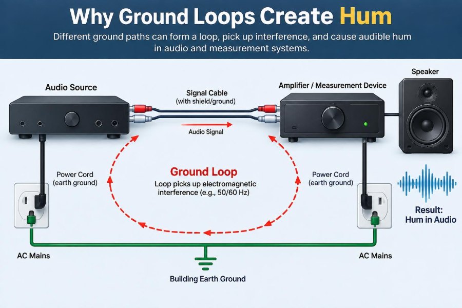
Imagine two devices connected by a signal cable. Both devices are also connected to protective earth through their power cords. The power-cord earth paths and the signal cable shield can make a loop.
If the two chassis have a small AC voltage difference, current may travel through one earth path, across the signal shield, and back through the other earth path. The shield then develops a voltage because it is not an ideal conductor.
That voltage can couple into the signal reference or directly modulate the input circuitry.
🛤️ 8. A Simple Equivalent Circuit
A useful model includes a source of unwanted voltage, impedances in each ground path, and the sensitive input that shares one of those paths. The interference source may be mains coupling, leakage current, magnetic induction, or current from another load.
The crucial point is not whether a loop can be drawn on paper. A problematic loop needs both a closed path and enough induced or imposed voltage to drive meaningful current.
Its effect also depends on where the receiving circuit establishes its signal reference.
🌀 9. Magnetic Fields Can Induce Hum
A loop formed by cables and chassis connections behaves like a receiving loop for changing magnetic fields. Power transformers, mains wiring, motor fields, and high-current conductors can induce voltage in that loop.
The induced voltage generally increases with loop area, field strength, and frequency. A wide separation between conductors can therefore be worse than a tightly routed pair.
This is one reason cable routing matters: moving a cable away from a transformer can improve a system even when no connection has changed.
🔌 10. Electric-Field Coupling Adds Another Path
Not all hum requires a conducting loop. An electric field from mains wiring can couple capacitively into a high-impedance input, an unshielded cable, or a floating metal object.
Capacitive coupling is often prominent when an input is left open or connected to a very high-impedance source. Touching the equipment can change the hum because the person’s body changes the capacitance to surrounding objects.
This can resemble a ground-loop fault, but its best remedy may be shielding or impedance reduction rather than changing an earth connection.
🧲 11. Transformer Placement Matters
Power transformers produce alternating magnetic fields. Audio transformers, pickup coils, and high-gain input circuits can receive those fields directly, even without a cable-related loop.
Rotating a transformer, increasing separation, or changing the orientation of sensitive equipment may reduce hum. This is a physical coupling problem, not necessarily a ground connection problem.
Good troubleshooting distinguishes magnetic pickup from circulating ground current so that effort is directed toward the actual mechanism.
📈 12. The Hum Frequency Gives Clues
A strong component at local mains frequency often points toward power-line coupling, magnetic pickup, or ground current related to the AC supply. Harmonics can make the sound more raspy or buzzy than a pure sine-wave hum.
Full-wave power-supply ripple commonly produces a component at twice the mains frequency. Switching supplies and digital systems can add higher-frequency tones, bursts, or broadband noise.
Frequency is evidence, not proof. A spectrum display or oscilloscope can help narrow the possibilities.
🎙️ 13. Balanced Audio Rejects Common-Mode Noise
A balanced connection carries the intended signal as a voltage difference between two signal conductors. Noise that appears equally on both conductors is called common-mode voltage.
A balanced receiver subtracts its two inputs, ideally rejecting common-mode interference. This is why balanced lines are preferred for professional audio, long cable runs, and electrically noisy environments.
However, balanced interfaces are not magical. Rejection depends on cable symmetry, source impedance balance, receiver performance, connector integrity, and frequency.
🧮 14. Common-Mode Rejection Has Limits
The ability of a differential input to reject equal interference is often described as common-mode rejection ratio, or CMRR. In practice, mismatched impedances convert part of a common-mode voltage into a differential error.
A damaged cable conductor, a poorly designed output stage, or unequal filtering at the receiver can reduce rejection. High common-mode voltage can also exceed an input stage’s allowable common-mode range.
Balanced wiring reduces susceptibility, but it does not excuse poor grounding or unsafe connections.
🧷 15. Cable Shields Have a Different Job
A shield is primarily intended to control electromagnetic interference by providing a low-impedance boundary around signal conductors. It may also act as a chassis bond, depending on the connector and equipment design.
In an unbalanced audio cable, the shield commonly serves as the signal return as well. That makes shield voltage particularly dangerous because the unwanted drop directly shares the signal reference.
In a balanced cable, the shield should ideally not carry the wanted signal current, which gives the system more immunity.
🪢 16. Shield Termination Is Frequency Dependent
At low frequency, designers may focus on resistance and circulating current. At radio frequency, inductance dominates, and a long thin “pigtail” shield connection can have surprisingly high impedance.
A broad, low-inductance bond to the chassis near the cable entry is generally effective for high-frequency shielding. Audio-frequency grounding requirements, safety requirements, and radio-frequency shielding requirements must be considered together.
This is why a rule such as “connect every shield at one end only” is too simplistic to apply universally.
🖥️ 17. Computer Connections Commonly Create Loops
A computer may connect to mains earth through its power supply, to a monitor through another cable, to audio equipment through USB or audio leads, and to network equipment through Ethernet. Each connection can introduce another reference path.
External displays, docking stations, powered speakers, USB audio interfaces, and chargers are frequent participants in hum problems. The noise may change when a laptop changes from battery power to charger power.
That observation is valuable because it points toward a path introduced by the charging arrangement.
🔬 18. Oscilloscope Ground Clips Need Special Care
On many bench oscilloscopes, the probe ground clip is connected to protective earth through the instrument’s power cord. Connecting that clip to a circuit node can force the node to earth potential.
In a grounded system, this may create a measurement ground loop. In a mains-referenced or improperly isolated circuit, it can cause equipment damage, tripped protection, or a serious shock hazard.
Before probing, verify the instrument grounding arrangement and the circuit’s reference. Never defeat protective-earth connections to make a measurement easier.
🛡️ 19. Safety Earth Must Not Be Removed
Removing the protective-earth pin or using an unsafe adaptor may appear to stop hum by breaking one current path. It also removes a critical fault-protection path from equipment designed to use it.
Exposed metal parts can become hazardous if an internal fault occurs. The apparent audio improvement is not evidence that the workaround is acceptable.
Fix signal interconnections and system architecture, not protective safety measures. Use equipment and isolation methods appropriate to the application.
🔁 20. Isolation Breaks Unwanted Galvanic Paths
Galvanic isolation prevents direct conductive current flow between two sides of an interface while still transferring the desired signal, power, or data. Audio transformers, isolated measurement amplifiers, optocouplers, and isolated digital interfaces are examples.
An audio isolation transformer can interrupt shield-related loop current while passing the audio signal magnetically. An isolated amplifier can measure a voltage at a remote reference without directly tying that reference to the data-acquisition ground.
Isolation has bandwidth, distortion, voltage-rating, and cost considerations, so it should be chosen deliberately.
🎚️ 21. Audio Transformers Are Practical Tools
A properly selected audio transformer can convert an unbalanced source to a balanced output, provide galvanic isolation, or interrupt a loop between two pieces of equipment. It can be highly effective where long analog interconnections are unavoidable.
Transformer performance depends on source and load impedance, level, frequency range, magnetic core behavior, and shielding. An unsuitable part can introduce low-frequency distortion, level loss, or high-frequency roll-off.
Used within its design range, it remains one of the most direct solutions to stubborn analog hum.
🧪 22. Differential Measurement Changes the Reference Problem
A differential measurement measures the voltage between two input terminals rather than assuming one terminal is the instrument’s ground. This is useful when the source is floating or sits at a different local potential.
The input amplifier must tolerate the common-mode voltage present on both terminals. It must also maintain adequate rejection when source impedances and wiring conditions are imperfect.
For higher voltages or hazardous systems, use probes, amplifiers, and instruments specifically rated for the expected voltage and installation category.
⭐ 23. Star Grounding Can Reduce Shared Impedance
In a star ground arrangement, sensitive returns meet at a controlled central point rather than sharing long sections with noisy load currents. The goal is to prevent one circuit’s return current from creating voltage errors in another circuit’s reference.
Star grounding is particularly useful at low frequencies in audio equipment and mixed-signal boards. It is not a universal geometry for all frequencies, because high-frequency current follows paths determined strongly by inductance and return-plane coupling.
The better rule is to control return-current paths for the frequencies involved.
🧱 24. Ground Planes Help When Used Thoughtfully
A continuous ground plane provides a low-impedance return path and reduces loop area between a signal trace and its return current. This usually improves both signal integrity and electromagnetic behavior.
Splitting a plane carelessly can force return current to take a long detour. That detour creates a larger loop, increasing inductance and radiated or received interference.
On printed-circuit boards, ground strategy is less about drawing symbolic ground connections and more about managing actual current paths.
📐 25. Cable Routing Changes Loop Area
Keep signal and return conductors close together. Twisted pair is effective because successive twists reduce the net area exposed to external magnetic fields.
Route sensitive analog cables away from mains transformers, power bricks, motor wiring, dimmers, and high-current conductors where practical. If power and signal must cross, crossing at roughly right angles can reduce parallel coupling length.
Neat routing is not only cosmetic; it can materially change a system’s noise behavior. 🧵
🕵️ 26. Diagnose One Connection at a Time
A disciplined process is more useful than randomly changing cables. Begin with a minimal working system, listen to or measure the baseline, then add one device or connection at a time.
- Check whether noise changes when equipment uses battery versus mains power.
- Disconnect signal cables while preserving safe power connections.
- Try a known-good balanced cable or a correctly specified isolator.
- Move cables and transformers to test for magnetic pickup.
- Observe the noise waveform and frequency when safe to do so.
Documenting each change prevents misleading conclusions.
🧩 27. Similar Symptoms Have Different Causes
Hum is a symptom, not a complete diagnosis. A ground loop is only one possible cause of unwanted low-frequency noise.
| Likely mechanism | Typical clue | Useful first check |
|---|---|---|
| Ground-loop current | Noise changes when an interconnecting cable is added | Check reference paths and isolation options |
| Magnetic pickup | Noise changes with equipment position or orientation | Increase distance from transformers |
| Capacitive pickup | High-impedance input hum changes when touched | Improve shielding and input reference |
| Power-supply ripple | Noise remains within one device without external signal leads | Inspect supply filtering and load conditions |
Correct identification prevents unnecessary and potentially unsafe changes.
🏭 28. Industrial Systems Need Reference Planning
Industrial installations combine long cable runs, motors, variable-speed drives, sensors, remote panels, and multiple power sources. A sensor ground reference may be separated by substantial distance from the controller ground.
Common approaches include isolated analog inputs, differential signaling, shielded twisted-pair cable, carefully planned shield bonding, segregated cable routes, and controlled chassis bonding. The details depend on frequency, environment, and equipment instructions.
Designing the reference architecture early is much easier than retrofitting noise fixes after installation.
🧠 29. The Core Principle: Control Current Paths
Ground loops create hum when unwanted current flows through an impedance shared with a signal reference, or when a physical loop receives electromagnetic energy. The resulting voltage is interpreted as part of the wanted signal.
The most reliable remedies reduce loop area, keep noisy return currents away from sensitive references, use balanced or differential interfaces, apply shielding correctly, and introduce rated isolation where a conductive path is not needed.
Protective earth remains essential for safety. A quiet system is achieved by controlling signal and return paths around it, not by defeating it.
When ground is treated as a real network of conductors, impedances, and currents rather than an ideal zero-volt symbol, hum problems become understandable and solvable. 🌍🎵🔧