
A microcontroller board works perfectly on a bench supply, then begins resetting when a motor starts nearby. An audio amplifier develops a faint hum as its battery runs down. A sensor reports values that drift whenever a radio transmitter sends a packet.
In each case, the circuit may have the correct nominal supply voltage, yet it does not have clean, stable power. Electronic components respond not only to the voltage printed on a battery or adapter label, but also to changing load current, ripple, noise, wiring resistance, and temperature.
Voltage regulators are the circuits that stand between an imperfect power source and the sensitive electronics that must operate from it. They absorb much of that uncertainty and deliver a controlled output voltage over a defined operating range.
Understanding how regulators work helps engineers choose appropriate parts, design reliable power layouts, diagnose failures, and avoid treating power delivery as an afterthought. ⚡
🔌 1. The Problem: Real Power Sources Are Not Ideal
An ideal voltage source would maintain exactly the same voltage regardless of how much current a circuit draws. Real batteries, USB adapters, solar panels, and mains-derived supplies cannot do that.
Their output can vary because of internal resistance, changing input conditions, switching activity, cable losses, and limitations in the source itself. A regulator reduces the effect of these variations at the load.
It does not create unlimited power. Instead, it controls the relationship between available input power and the required output voltage.
🎯 2. What a Voltage Regulator Does
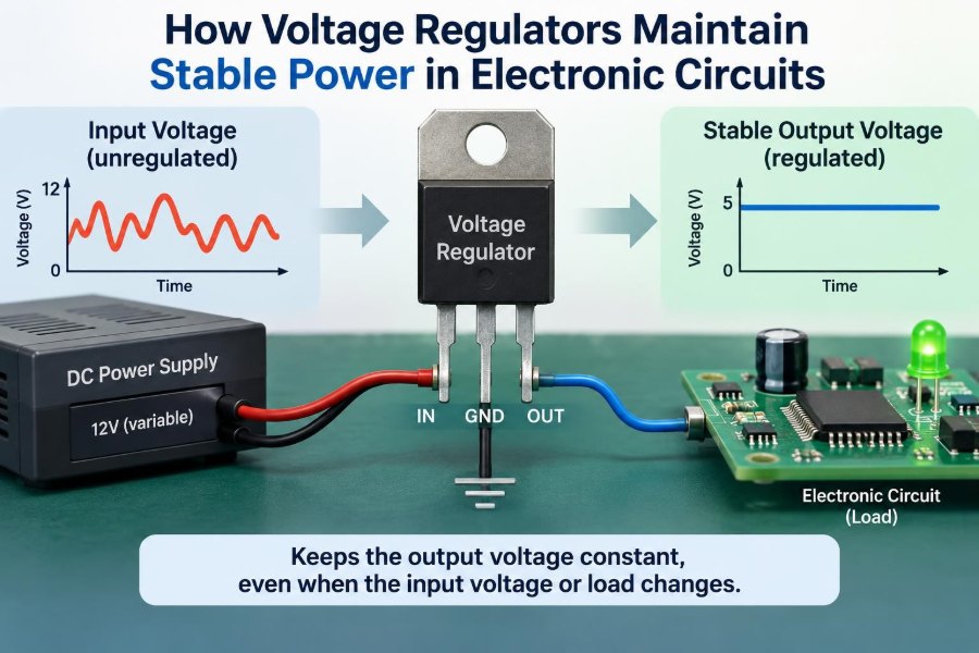
A voltage regulator is a feedback-controlled power circuit that attempts to hold its output at a chosen value, such as 5 V, 3.3 V, 1.8 V, or an adjustable level.
It continuously senses the output, compares it with an internal reference, and changes its control element when the output moves away from the target. This is called closed-loop regulation.
If the load suddenly demands more current and the output begins to fall, the regulator reacts by allowing more energy to reach the load. If the output rises, it reduces that energy transfer.
📏 3. Regulation Begins with a Reference Voltage
Every regulator needs a stable target against which it can judge the output. Internally, that target is provided by a reference voltage, designed to vary much less than the unregulated input.
The reference may be generated by a bandgap circuit, a precision reference structure, or another temperature-compensated arrangement. The exact implementation differs, but the purpose is the same: establish a dependable internal yardstick.
Without a reference, a regulator would have no reliable definition of what “correct voltage” means.
🔍 4. The Feedback Divider Measures the Output
Many adjustable regulators use two resistors as a feedback divider. The divider scales the output voltage down to a level that can be compared with the internal reference.
For a simple divider, the sensed voltage is determined by the resistor ratio. When the sensed value equals the reference, the output is at its intended setpoint.
Vout = Vref × (1 + Rupper / Rlower)
This familiar relationship is simplified; some devices include an additional small current term or use a different feedback arrangement. The data sheet always defines the actual design equation.
⚖️ 5. The Error Amplifier Detects Differences
The error amplifier compares the feedback voltage with the reference. Its output represents the error: the difference between the voltage the regulator sees and the voltage it wants to see.
When output voltage is too low, the amplifier drives the control system in a direction that raises it. When output voltage is too high, it drives the system in the opposite direction.
This continuous comparison is the central mechanism behind voltage regulation. A regulator is not merely a voltage-dropping component; it is an active control system.
🚪 6. The Pass Element Controls Energy Flow
In a linear regulator, the control element is commonly a transistor operating as a variable pass device. It behaves somewhat like an automatically adjusted valve between input and output.
The error amplifier changes the transistor’s drive so that the transistor drops more or less voltage. The load receives the remaining voltage at the output.
Because the pass transistor can operate in a partially on state, it dissipates power as heat. That makes linear regulation simple and quiet, but not always efficient.
📉 7. How a Linear Regulator Corrects a Voltage Drop
Imagine a 5 V linear regulator powering a digital circuit. When the circuit changes state, it may briefly draw additional current from the output capacitor and regulator.
The output voltage tends to dip. The feedback divider reports a lower sensed voltage, the error amplifier detects the error, and the pass element is driven harder to supply more current.
The response is not instantaneous, but a well-designed control loop corrects the disturbance quickly enough to keep the output within the load’s acceptable range.
🔄 8. Switching Regulators Use Stored Energy
Switching regulators regulate voltage differently. Rather than continuously burning the excess voltage across a pass transistor, they rapidly switch a transistor on and off and control the transfer of energy through inductors, capacitors, and sometimes transformers.
By adjusting switch timing, current limits, or pulse width, the controller maintains the desired average output voltage. The switching action is efficient because the main switch spends much of its time either fully on or fully off.
The trade-off is greater circuit complexity and the need to manage ripple, electromagnetic interference, and layout carefully.
⬇️ 9. Buck Converters Step Voltage Down
A buck converter produces an output lower than its input. It is often used to convert a higher battery, adapter, or intermediate bus voltage into logic or processor rails.
When its switch turns on, inductor current rises and energy is stored in the magnetic field. When the switch turns off, the inductor resists the sudden current change and continues delivering energy to the load.
A diode or synchronous transistor provides the current path during the off interval. The controller observes output feedback and adjusts the switching duty cycle.
⬆️ 10. Boost Converters Step Voltage Up
A boost converter produces an output higher than its input. Common examples include circuits that generate 5 V from a single-cell battery or create a high-voltage rail for a display or LED string.
While the switch is on, the inductor stores energy. When it turns off, the inductor’s voltage reverses as needed to maintain current, adding to the input voltage and transferring energy to the output.
A boost converter cannot usually regulate properly if the input remains above the intended output, because its basic power path can allow input energy to reach the output directly.
🔃 11. Buck-Boost Topologies Handle Changing Inputs
Battery-powered systems often face an input voltage that can be above, near, or below the desired output. A buck-boost converter is designed to regulate across that transition.
Different topologies use different arrangements of switches, inductors, and capacitors. Some invert the output polarity, while non-inverting versions preserve a positive output relative to ground.
This flexibility is valuable, but selection requires attention to current capability, efficiency across the input range, control mode, and the device’s behavior during startup.
🧭 12. Feedback Is a Control Loop, Not a One-Time Adjustment
Regulation is dynamic. The output may be disturbed many times each second by processor activity, radio bursts, motor motion, or changes at the input.
The feedback loop repeatedly measures, compares, and corrects. Its quality depends on how rapidly and accurately it responds without becoming unstable.
Engineers describe this behavior using control concepts such as loop gain, bandwidth, phase margin, and transient response. These ideas explain why an apparently correct schematic can still produce an oscillating power rail.
🌀 13. Compensation Keeps the Loop Stable
Inductors, capacitors, transistor stages, and load resistance introduce delays and phase shifts into a regulator’s feedback path. If the corrective action arrives with too much delay, it can reinforce the disturbance rather than remove it.
Compensation shapes the loop response to provide stable control. It may be integrated into a regulator IC, set by external resistor-capacitor components, or partly determined by the output capacitor and its equivalent series resistance.
Never assume that any capacitor value will work. A regulator’s documentation specifies stable ranges, component types, and recommended layouts.
📊 14. Load Regulation Describes Current-Dependent Change
Load regulation describes how much the output voltage changes as load current changes, usually from a light-load condition toward a specified maximum load.
A nonzero change is normal because every real regulator, transistor, wire, and capacitor has resistance and finite control-loop gain. The goal is to keep the change within the needs of the circuit.
Digital logic may tolerate a different voltage range from an analog reference, RF circuit, or precision sensor. “Good regulation” therefore depends on the application.
🌦️ 15. Line Regulation Describes Input-Dependent Change
Line regulation measures how well a regulator holds the output when its input voltage changes while the load is held constant. For example, an adapter voltage may rise or fall as mains conditions and loading change.
A regulator with good line regulation prevents most of that input movement from appearing at the output. It does so through feedback and through the inherent rejection properties of its circuit architecture.
Line regulation should be considered across the actual input range, not only at one convenient nominal voltage.
🌊 16. Ripple and Noise Are Different Power Problems
Ripple is a periodic variation on a supply rail, often associated with rectified mains supplies or switching converters. Noise is a broader term for unwanted random, broadband, or high-frequency voltage disturbances.
A regulator can reduce some input ripple, but its effectiveness depends on frequency, operating conditions, and circuit type. Linear regulators are often selected after switching pre-regulators to clean a sensitive low-current rail.
Capacitors, filters, grounding, shielding, and physical layout also matter. A regulator alone cannot solve every noise problem. 🔊
🛡️ 17. PSRR Shows Rejection of Input Disturbances
Power-supply rejection ratio, or PSRR, expresses how effectively a circuit prevents disturbances on its input supply from appearing at its output. It is commonly discussed for linear regulators, amplifiers, and analog integrated circuits.
PSRR changes with frequency. A regulator that rejects low-frequency ripple well may be less effective against high-frequency switching noise.
For sensitive analog rails, examine PSRR graphs at frequencies relevant to the upstream converter, clocks, and interference sources. Input and output capacitors must be chosen as part of the complete filtering system.
🧱 18. Output Capacitors Support Fast Load Changes
A regulator cannot instantly increase its current when a load changes. The output capacitor supplies or absorbs current during the first moments of a transient.
When load current steps upward, the capacitor initially provides some extra current and limits the voltage dip. When the load current falls, it absorbs excess energy and limits overshoot while the control loop reduces delivery.
Capacitance, equivalent series resistance, equivalent series inductance, and placement all affect this behavior. A large capacitor placed far away may be less helpful than a suitable capacitor close to the load.
📥 19. Input Capacitors Protect the Regulator’s Supply Path
The input of a regulator also needs local energy storage. An input capacitor reduces input voltage disturbance caused by fast switching currents or resistance in cables and PCB traces.
For a switching regulator, it is especially important that the high-current switching loop between input capacitor, switch, and return path is physically compact. Long paths add inductance and can create ringing and radiated interference.
Place recommended input capacitors close to the IC pins, then use bulk capacitance elsewhere when the source is distant or the load has slower, larger current demands.
🔥 20. Linear Regulators Turn Voltage Difference into Heat
The main loss in a linear regulator is approximately the voltage drop across it multiplied by load current.
Ploss ≈ (Vin − Vout) × Iout
If a regulator reduces 12 V to 5 V at substantial current, much of the input power becomes heat in the package. Thermal limits may be reached even when the electrical current rating appears adequate.
Heat sinking, copper area, airflow, ambient temperature, and package thermal resistance determine whether the device can operate safely. Always calculate worst-case dissipation.
⚡ 21. Switching Efficiency Has Practical Limits Too
Switching converters can be highly efficient, especially when the input-output voltage difference is large. Yet they still lose power in transistor resistance, diode drops, inductor resistance, switching transitions, gate drive, and control circuitry.
Efficiency also changes with input voltage and load current. At very light loads, the controller’s own operating current and pulse-skipping behavior may become important.
Selecting a switching regulator is not simply choosing the highest advertised efficiency. Output noise, cost, size, quiescent current, transient response, and EMI requirements may matter just as much.
🚧 22. Dropout Voltage Limits Linear Regulation
A linear regulator needs some voltage difference between input and output to control its pass element. This minimum required difference is called dropout voltage.
When the input falls too close to the desired output, the regulator can no longer compensate fully. The output then follows the input downward, minus losses in the pass device and wiring.
Low-dropout regulators, or LDOs, are designed to operate with a smaller input-output difference than older regulator structures. Their dropout still depends on load current and temperature.
🧮 23. Current Rating Is Not the Whole Design Limit
A regulator specified for a certain output current may not deliver that current under every combination of input voltage, output voltage, temperature, and PCB design. Thermal dissipation, dropout, inductor saturation, and current-limit behavior can all reduce practical capability.
For switching regulators, distinguish between switch current limit, inductor peak current, and guaranteed continuous output current. These are related but not identical quantities.
Also consider startup and fault currents. Motors, capacitive loads, LEDs, and downstream converters can demand more current briefly than their steady-state ratings suggest.
🧯 24. Protection Features Improve Survival, Not Immunity
Many regulator ICs include protection functions such as current limiting, thermal shutdown, short-circuit protection, undervoltage lockout, reverse-current blocking, or soft start. These features can prevent damage during predictable fault conditions.
However, their behavior varies by device. Thermal shutdown may cycle the output on and off, current limiting may be foldback or constant-current, and reverse-current protection may be absent.
Protection should not replace appropriate fuses, transient suppression, polarity protection, wiring design, or a considered fault analysis.
🗺️ 25. PCB Layout Is Part of the Regulator Circuit
A regulator schematic does not show trace inductance, shared return paths, copper resistance, or electromagnetic coupling, but the finished board contains all of them. At switching frequencies and fast load edges, these parasitics strongly affect performance.
Keep sensitive feedback traces away from noisy switch nodes. Use short, wide high-current paths, place local capacitors close to relevant pins, and provide a low-impedance return path.
For adjustable regulators, take feedback from the quiet output point rather than a point corrupted by load-current voltage drop. This practice is often called remote sensing when implemented deliberately.
🧪 26. Measuring a Regulated Supply Correctly
A digital multimeter is useful for checking the average output voltage, but it can miss short dips, ripple, oscillation, and startup events. An oscilloscope is often required to investigate regulation problems.
Probe technique matters. A long ground lead can act as an antenna and falsely show ringing. Use a short ground spring or a carefully arranged low-inductance connection when examining high-frequency ripple.
Useful checks during validation
- Measure output voltage at minimum, typical, and maximum load.
- Check startup, shutdown, and load-step behavior.
- Observe ripple with appropriate bandwidth and probing.
- Verify input voltage at the regulator pins, not only at the source.
- Test across expected temperature and input conditions when possible.
🧩 27. Choosing Between Linear and Switching Regulation
The best regulator architecture depends on the electrical and physical constraints of the product. The comparison below gives a useful starting point, but device-specific behavior remains important.
| Consideration | Linear regulator | Switching regulator |
|---|---|---|
| Efficiency with large voltage drop | Usually poor | Usually better |
| Circuit complexity | Often lower | Usually higher |
| Output noise | Often lower, but not automatically quiet | Requires ripple and EMI management |
| Heat dissipation | Can be significant | Usually lower for equivalent conversion |
| Voltage conversion | Typically step-down only | Can step down, step up, invert, or buck-boost |
A common design uses both: a switching converter creates an efficient intermediate rail, and an LDO supplies a particularly noise-sensitive, lower-current circuit.
🧠 28. The Core Principle: Sense, Compare, Correct
Whether a regulator is a simple LDO, a synchronous buck converter, or a complex multiphase supply, its fundamental task is the same. It senses the output, compares that measurement with a stable reference, and corrects energy flow through a feedback loop.
The surrounding components make that principle practical. Capacitors handle rapid current changes, inductors store energy in switching designs, compensation preserves stability, protection handles faults, and PCB layout prevents parasitic effects from undermining the loop.
A stable power rail is the result of a complete control system, not just a regulator IC with the right output label. Design the source, regulator, capacitors, load path, thermal path, and measurement method as one system. 🔋⚙️📈