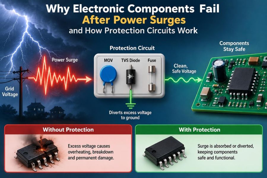

A router stops working after a thunderstorm. A television that was fine yesterday will no longer turn on after the utility power returns. In a workshop, a motor controller fails just after a nearby contactor switches off.
These events may look unrelated, but each can expose electronics to an electrical transient: a short-lived voltage or current disturbance that exceeds what a circuit was designed to tolerate. The visible event may last microseconds, yet the damage can be immediate or quietly shorten a product’s life.
Power surges matter because modern devices run on increasingly low voltages while connecting to long cables, mains wiring, motors, chargers, and communication ports. A tiny microcontroller pin may operate at only a few volts, but it can be connected indirectly to an environment capable of producing much larger disturbances.
Protection circuits do not make equipment invulnerable. Their job is more practical: give surge energy a controlled path, keep sensitive nodes below damaging limits, and coordinate the response of several components before heat or excessive electric field reaches the load.
⚡ What a Power Surge Actually Is
A power surge is a temporary increase in voltage beyond the normal operating level of a supply or signal line. It is often called an overvoltage transient because it rises and falls quickly rather than remaining elevated like a persistent supply fault.
Surges differ in amplitude, duration, source impedance, and available energy. A brief, high-voltage pulse from electrostatic discharge behaves very differently from a mains transient caused by lightning or utility switching, even if both can damage electronics.
📈 Voltage Alone Does Not Describe the Threat
Voltage is what first attracts attention, but damage depends on more than the peak value. The source’s ability to deliver current, the pulse duration, the circuit impedance, and the protected device’s construction all affect the outcome.
A high-voltage pulse from a very weak source may create little heating. Conversely, a lower-voltage surge with substantial available current can overheat traces, rectifiers, and power semiconductors. Surge design therefore considers both clamping voltage and energy handling.
🌩️ Common Sources of Surge Energy
Lightning is the best-known source, but it is not the only one. A direct strike is extreme; more commonly, a nearby strike induces voltage in building wiring or causes large ground-potential differences between connected equipment.
- Utility switching, fault clearing, and restoration of service can disturb mains voltage.
- Motors, relays, solenoids, and transformers store magnetic energy and release it when current changes abruptly.
- Electrostatic discharge occurs when a charged person or object touches a connector.
- Long outdoor cables can collect induced energy and carry it indoors.
- Poorly controlled hot-plugging can create inrush, ringing, or ground-bounce transients.
The source helps determine where protection belongs. A relay coil needs local suppression, while an exposed communications port needs protection at the physical entry point.
🧲 Why Inductive Loads Create Voltage Spikes
Inductors resist a sudden change in current. A motor winding, relay coil, and solenoid all store energy in a magnetic field while energized. When a switch opens, the inductor attempts to keep current flowing.
If no safe path exists, the voltage rises until current finds one, perhaps by arcing across switch contacts or breaking down a transistor. This is why a coil can generate a damaging spike from a modest DC supply.
A flyback diode across a DC coil provides a recirculation path. It limits voltage effectively, although it can slow coil release; circuits requiring faster release may instead use a diode with a zener clamp or another deliberately higher-voltage suppressor.
🧤 Electrostatic Discharge Is Fast but Local
Electrostatic discharge, or ESD, is the small spark felt after walking on carpet and touching metal. It can involve very high voltage, but its energy is usually limited and its rise time is extremely fast.
Integrated circuits often include tiny internal ESD structures, yet those structures are intended for limited handling events, not repeated exposure from an unprotected external cable. USB, HDMI, Ethernet, antenna, and sensor connectors commonly need external low-capacitance ESD protection.
🔌 The Difference Between Surge, ESD, and Inrush
These terms are sometimes used interchangeably, which leads to unsuitable protection choices. They describe different electrical stresses and may need different tests and components.
| Disturbance | Typical character | Common design response |
|---|---|---|
| ESD | Very fast discharge from a charged body or object | Low-inductance TVS diode near connector |
| Surge | Higher-energy transient from wiring, switching, or lightning effects | Coordinated MOV, TVS, GDT, fuse, or impedance |
| Inrush current | Startup current into capacitors or transformers | NTC, active limiter, soft-start circuit |
| Overvoltage fault | Sustained abnormal supply voltage | Disconnect, crowbar, monitor, rated regulator |
A part that survives an ESD event is not automatically suitable for a high-energy mains surge, and a surge arrester is not necessarily fast or low-capacitance enough for a high-speed data line.
🔥 How Excess Voltage Damages Silicon
Semiconductor devices contain thin insulating layers and tightly spaced junctions. When voltage exceeds a rating, the electric field can rupture an oxide layer, force a junction into breakdown, or trigger unwanted conduction paths.
The result may be an immediate short circuit, an open circuit, or a subtle parameter shift. A damaged MOSFET gate oxide, for example, may leak more current without failing visibly at first. Repeated stress can turn that weakened device into a later field failure.
🌡️ Heat Is Often the Final Failure Mechanism
Even when the initiating event is electrical, damage often becomes thermal. Current through a resistance produces heat, and a short pulse can concentrate that heat in a microscopic part of a chip, bond wire, resistor film, or copper trace.
Energy absorption is especially relevant for suppressors. A device may clamp the voltage successfully but fail if it must absorb more pulse energy than its construction can tolerate. Its data sheet pulse conditions matter; a single headline wattage is not a universal rating.
🧱 Insulation Breakdown and Creepage Failures
High voltage can also travel where designers did not intend. It may arc across contaminated boards, through inadequate spacing, or across damaged insulation. Moisture, dust, flux residue, and conductive debris can reduce the practical margin.
Clearance is the shortest distance through air between conductors. Creepage is the distance along an insulating surface. Both matter in mains-connected designs, and required values depend on voltage, environment, insulation system, and applicable safety requirements.
🕳️ Why Components Sometimes Fail Days Later
Not every surge produces a dramatic burn mark. A transient can partially degrade a semiconductor junction, capacitor dielectric, or connector contact. The product appears normal until temperature, normal loading, or another smaller event pushes the weakened part beyond its limit.
This delayed behavior complicates troubleshooting. Replacing an obviously failed controller without identifying the incoming path may simply expose the replacement to the same stress.
🧭 Finding the Surge Entry Path
Surge energy enters through conductors and through coupling between conductors. The mains input is an obvious path, but signal lines, shield connections, cable screens, and even nearby high-current traces can carry or induce a disturbance.
When investigating a failure, ask where the transient entered, where it returned, and what components sat along that route. A protection part connected to the wrong return path can leave the protected integrated circuit exposed despite being present on the schematic.
🛑 The Basic Idea of Clamping
A clamping device stays mostly inactive during normal operation. Above a threshold, it conducts strongly enough to divert current away from the sensitive load and hold the protected node near a safer voltage.
“Near” matters. No real clamp holds a perfectly fixed voltage. Its voltage rises with current, connection inductance, temperature, and pulse shape. The protected component must tolerate the actual residual voltage, not just the suppressor’s nominal label.
📉 TVS Diodes for Fast Local Protection
A transient-voltage-suppression diode, or TVS diode, is designed to enter avalanche conduction quickly during an overvoltage event. It is widely used on DC rails, automotive lines, and I/O interfaces because it can clamp fast pulses at a predictable location.
Selecting one requires more than choosing a voltage number. The reverse standoff voltage must exceed normal operating voltage, its breakdown and clamping behavior must suit the protected circuit, and its pulse-current capability must match the expected threat. Capacitance can also matter greatly on fast data lines.
🟦 MOVs for Energy on AC Inputs
A metal-oxide varistor, or MOV, is a voltage-dependent resistor commonly placed across AC mains inputs. As voltage rises, its resistance falls and it shunts surge current, making it useful where moderate-to-high surge energy is expected.
MOVs age as they absorb repeated surges. Their characteristics can shift, and a severely stressed device may overheat or fail short. In mains equipment, an MOV is often paired with a fuse, thermal disconnect, or specially protected MOV arrangement so its end-of-life behavior does not become a fire hazard.
🫧 Gas Discharge Tubes for Large Pulses
A gas discharge tube, or GDT, contains electrodes in a sealed gas-filled enclosure. When its spark-over condition is reached, it becomes highly conductive and can divert substantial surge current.
GDTs are useful on telecommunications and exposed lines, but they generally act more slowly and have less precise voltage control than a TVS diode. A common coordinated approach uses a GDT to handle bulk energy and a downstream TVS diode to limit the remaining fast voltage at sensitive electronics.
🧯 Fuses and PTCs Have a Different Job
A fuse does not normally clamp a brief voltage spike. Its central purpose is to open when excessive current persists long enough to heat its element. It protects wiring and limits fault energy after a suppressor or failed component starts drawing sustained current.
A resettable polymer PTC increases resistance when heated by overcurrent and may recover after power is removed. It is convenient in some low-voltage products, but it reacts more slowly than a semiconductor clamp and is not a substitute for surge suppression.
🚨 Crowbars Disconnect by Deliberate Shorting
A crowbar circuit reacts to an overvoltage by creating a low-resistance path across the supply, usually forcing a fuse or current-limited source to shut down. A silicon-controlled rectifier is a classic example in certain DC power systems.
This sounds counterintuitive, but it can protect a sensitive load from a sustained regulator failure that a simple shunt clamp could not safely absorb. The supply, wiring, fuse coordination, and reset procedure must all be designed for this behavior.
🧰 Series Impedance Limits the Current
Protection is not only about shunting energy away. A series resistor, ferrite bead, inductor, common-mode choke, or deliberately selected trace impedance can reduce the current that reaches a clamp or sensitive input.
For example, a small series resistor ahead of an ADC input and its clamp diodes can limit injection current during an abnormal signal. The resistor must still satisfy normal accuracy, bandwidth, noise, and source-impedance requirements.
🧩 Internal Clamp Diodes Need External Help
Many IC pins include diodes to the supply rails. They can steer small transient currents away from the input structure, but they are usually not intended to absorb a cable-borne surge by themselves.
If an external signal rises while the IC is unpowered, those diodes can unintentionally back-power the device. Series resistance, external clamps, and a defined power-sequencing strategy prevent this from becoming a hidden reliability problem.
🏗️ Layered Protection Works Better Than One Hero Part
Robust designs often use several protection stages, each with a different task. An entry-stage device handles the largest energy, impedance limits follow-on current, and a local clamp protects the final low-voltage node.
This is called coordination. The upstream device must begin conducting early enough to reduce energy, while the downstream device must survive the remaining pulse without being forced to absorb everything. Component tolerances and lead inductance influence the sharing.
📍 Placement Can Decide Whether Protection Works
A TVS diode placed far from a connector may be electrically distant even if the schematic looks correct. Fast transient current flowing through a long, narrow trace produces voltage due to resistance and inductance, leaving the IC exposed to a higher local voltage.
Place the first clamp close to the entry point, use short and wide return paths, and keep its path to chassis or reference plane low inductance. Then route the protected signal onward. Do not route the unprotected line past the vulnerable IC before it reaches the clamp.
⏱️ Fast Edges Make Parasitics Visible
Every trace and component lead has small parasitic resistance, inductance, and capacitance. During normal low-frequency operation these effects may seem negligible. During a fast surge edge, they can dominate the voltage distribution.
The relationship V = L × di/dt explains why rapidly changing current creates voltage across inductance. A few extra millimeters in a clamp return path can therefore reduce protection performance, particularly against ESD.
🌍 Ground, Chassis, and Return Paths Are Not Interchangeable
“Ground” is a convenient label, not a guarantee that every grounded point stays at the same voltage during a surge. High current can create substantial differences between locations on a return conductor.
For equipment with a metal enclosure, it is often preferable for incoming high-energy transients to be diverted to chassis near the entry point, rather than sent across the sensitive signal ground. The appropriate connection strategy depends on isolation, EMC requirements, safety design, and the product’s physical construction.
🔋 DC Power Rails Need Their Own Strategy
A DC input can see reverse polarity, load dump in vehicle systems, adapter faults, cable hot-plugging, and inductive spikes. A typical front end may combine a fuse or PTC, reverse-polarity protection, a TVS diode, filtering, and a regulator rated for the expected input conditions.
Capacitors help with slower disturbances but are not universal surge suppressors. Their equivalent series resistance and inductance limit their response at high frequency, and an excessive pulse can exceed their voltage or ripple-current ratings.
🏠 Mains Protection Requires Safety Thinking
Mains-connected protection has two simultaneous goals: preserve electronics and prevent hazardous failure. Component ratings, isolation barriers, enclosure design, flame behavior, fusing, and spacing must be considered together.
Never add a mains MOV, capacitor, or surge circuit to equipment without understanding its voltage rating, fault behavior, and relevant safety requirements. Work on mains-powered equipment can involve lethal energy even when the intended repair seems simple; qualified review and proper test equipment are appropriate.
📡 Protecting Data and Communication Ports
Data interfaces have a trade-off that power inputs often do not: protection components can distort the signal. Excess capacitance can slow edges, affect impedance, and reduce margin on high-speed links.
Choose interface-specific protectors with suitable capacitance and channel arrangement. Keep differential-pair routing symmetric where relevant, place the protector at the connector, and ensure the discharge path does not run through the receiver’s reference plane.
🧪 Reading Protection Component Data Sheets
Data sheets use terms that must not be confused. For a TVS diode, reverse standoff voltage describes normal off-state operation; breakdown voltage is where significant avalanche begins; clamping voltage is specified at a stated pulse current.
Check the test waveform behind every surge rating. Also review leakage, capacitance, temperature derating, package thermal limits, and repetitive-pulse capability. A design based only on a single maximum number can be misleading.
🔍 Testing Without Creating a New Failure
Testing protection circuits is valuable, but improvised high-voltage experiments can destroy instruments, create shock hazards, or produce conclusions that do not represent real conditions. Use controlled test methods and equipment appropriate to the product category.
For bench troubleshooting, begin with safer checks: inspect for cracked MOVs or scorched resistors, measure obvious shorts with power removed, compare rail resistance with a known-good board, and verify that clamps are not shorted or leaking abnormally. A failed suppressor is evidence of stress, not necessarily the original cause.
🛠️ A Practical Design Workflow
- Define every external interface and the environment in which the product will operate.
- Identify credible transient sources, including local inductive loads and cable exposure.
- Determine what the protected IC, regulator, and passive parts can tolerate.
- Select a layered clamp-and-impedance approach with normal operation in mind.
- Lay out the high-current surge path before optimizing minor routing details.
- Review fault behavior, thermal limits, and service consequences.
- Validate with representative tests and revise from measured waveforms where possible.
This workflow prevents a common mistake: treating protection as a last-minute component added after the layout is already fixed.
❌ Common Protection Mistakes
- Choosing a TVS standoff voltage below the highest normal supply voltage, causing leakage or premature conduction.
- Choosing a clamp voltage above what the downstream semiconductor can survive.
- Using a physically powerful suppressor with a long, inductive ground connection.
- Assuming a fuse protects against an ultrafast transient.
- Relying on an IC’s internal diodes for energy arriving through a long external cable.
- Ignoring suppressor aging, especially on repeatedly stressed AC inputs.
- Forgetting that a protection device can affect signal integrity, leakage, or startup behavior.
Most of these errors are not caused by a lack of components. They come from overlooking the full current path and the difference between a laboratory schematic and a physical product.
🧠 Matching the Protection to the Failure Mechanism
The best protection circuit is not the one with the most parts. It is the one whose components respond to the actual threat, remain quiet during normal operation, and fail safely if their limits are exceeded.
A relay driver may need a diode close to its coil. An outdoor sensor port may need a surge arrester, common-mode impedance, and local TVS devices. A mains supply may need coordinated input protection and safe disconnection. Context determines the answer.
✅ The Core Principle: Control Energy and Its Path
Electronic components fail after power surges when voltage, current, electric field, or heat exceeds the margin built into their materials and structures. The resulting fault can be immediate, intermittent, or delayed by accumulated damage.
Protection circuits work by steering transient current, limiting residual voltage, slowing harmful current rise, and disconnecting faults when necessary. Their effectiveness depends on ratings, coordination, placement, and return-path layout—not merely on placing a “surge protector” symbol on a schematic.
When a design treats the surge path as deliberately as its normal power path, protection becomes a measurable engineering function rather than a hopeful add-on.
Reliable surge protection comes from understanding where energy originates, where it can flow, and which component must safely handle each part of the event. That perspective turns mysterious post-surge failures into solvable design and troubleshooting problems. ⚡🛠️🔌