
A laptop charger can deliver far more power than an old USB port ever could. Yet the same USB-C connector might be plugged into wireless earbuds, a phone, a monitor, a power bank, or a development board.
That flexibility raises an important safety question: how does a 5 V device avoid being exposed to 20 V, 28 V, or another higher charging voltage? The answer is not a guess based on charger size or cable shape. It is a carefully sequenced digital negotiation system called USB Power Delivery, usually shortened to USB PD.
USB-C Power Delivery lets connected equipment advertise capabilities, request an appropriate operating point, verify the request, and change the power path only when both ends agree. Understanding that sequence helps engineers design reliable products and helps users understand why USB-C charging behavior can vary.
At its core, the system follows a simple rule: a source must not raise VBUS above the safe default until a compatible sink has explicitly asked for, and been granted, a higher-voltage contract. ⚡
🔗 1. USB-C Is a Connector, Not Automatically a Power Level
USB-C defines a reversible connector and cable ecosystem. It does not by itself mean that every port supports high power, rapid charging, video output, or USB Power Delivery.
A USB-C port can provide only basic 5 V power, while another port with the same physical shape can support several voltage and current combinations through PD. Product designers must therefore specify the supported behavior rather than relying on the connector name alone.
⚡ 2. Why Higher Voltage Is Useful
For a given power level, raising voltage allows lower current. Since cable and connector heating are strongly affected by current, this can make it practical to deliver substantial power through a compact cable.
For example, a computer may need more power than 5 V at a few amperes can conveniently provide. A higher-voltage PD contract can meet that need while keeping current within the cable and connector ratings.
Higher voltage is useful, but it is never assumed to be safe for every attached product. That is why negotiation comes first.
🛡️ 3. The Safe Starting Point: Default USB Power
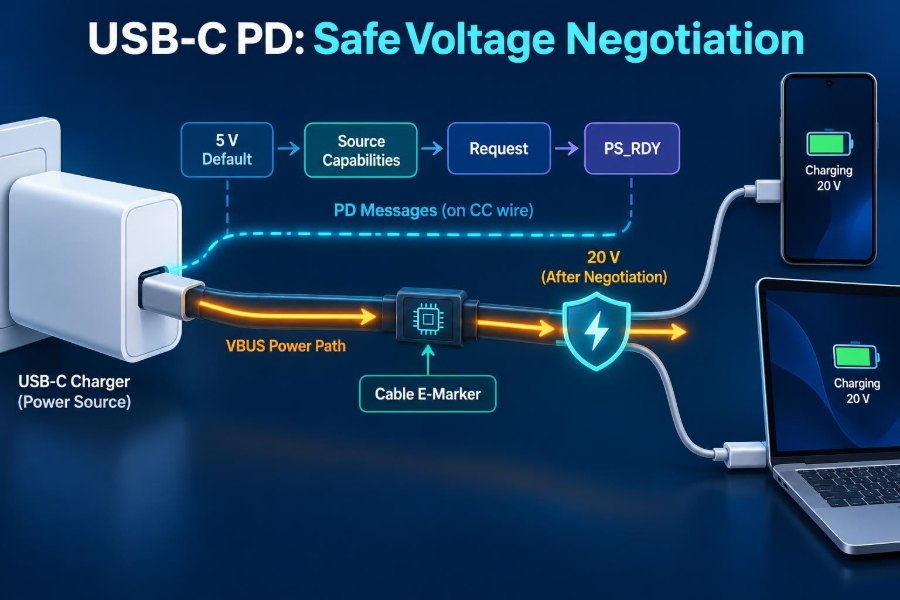
Before a PD contract is established, VBUS begins at a safe default USB voltage: nominally 5 V. This is the baseline that allows ordinary USB-C devices to connect without needing to tolerate higher voltages.
A source does not simply place 20 V on VBUS because it is capable of doing so. The sink must participate in communication and request a supported power option before the source transitions upward.
This default-first behavior is the most important safety property of USB-C charging.
📌 4. CC Pins Detect the Connection
USB-C includes two Configuration Channel, or CC, pins: CC1 and CC2. Because the plug is reversible, only one is normally connected through a standard cable in a particular orientation.
The source watches the CC pins for a pull-down resistor called Rd from an attached sink. This tells the source that a device requesting power has been connected.
The CC connection also helps establish plug orientation and can support other functions, including cable identification and power-role behavior.
🔍 5. Rp and Rd Establish Basic USB-C Current
A source presents a pull-up arrangement called Rp on its CC pin. The detected CC voltage indicates the basic current level the source is willing to provide at 5 V before PD negotiation.
This initial USB-C current advertisement is separate from a full PD power contract. A sink can use it to determine what it may draw at the default voltage, even if neither device implements USB PD messaging.
- Rd identifies a sink attached to a source.
- Rp advertises the source’s default-current capability.
- 5 V VBUS remains the starting power level.
💬 6. Power Delivery Uses Digital Messages
Once connected, PD-capable devices exchange structured messages over the active CC wire. This communication is independent of the main VBUS power conductor.
In normal operation, the source announces its available power options, and the sink selects one. These messages are protected by protocol mechanisms intended to make corrupted or incomplete communication detectable rather than silently acted upon.
PD is therefore an active agreement, not merely an analog voltage indication.
📨 7. Source Capabilities Describe Available Options
A PD source sends a Source_Capabilities message containing one or more Power Data Objects, or PDOs. Each PDO describes a power option the source can offer.
Common fixed PDOs describe a particular voltage and a maximum current. A charger may advertise 5 V plus one or more higher fixed voltages, but a sink is not required to use every option.
The source’s advertised list is a limit, not a command. The sink remains responsible for choosing an option it can safely accept.
🧾 8. The Sink Requests One Specific Contract
After examining the offered PDOs, the sink transmits a Request message. It identifies the selected PDO and states the current or power it intends to use within the advertised limit.
A well-designed sink considers its battery state, converter efficiency, thermal conditions, system load, and cable limitations. It may request less than the source’s maximum capability when that is the better engineering choice.
The requested operating point becomes the proposed power contract.
✅ 9. Accept Is Not Yet Permission to Draw Full Power
If the source can satisfy the request, it sends Accept. This confirms that the requested contract is valid, but it does not necessarily mean the new VBUS level has already settled.
The source may need to reconfigure its power converter, enable a different regulation setting, or verify that its output is stable. During that interval, the sink must follow the protocol’s timing and state rules.
This distinction prevents the receiving device from treating a planned voltage change as an instantaneous one.
🚦 10. PS_RDY Marks a Completed Transition
When the requested supply condition is ready, the source sends PS_RDY, meaning Power Supply Ready. This message marks completion of the power transition.
Only after the appropriate sequence is complete should the sink rely on the newly negotiated voltage and draw power according to that contract. The handshake is therefore:
- Source advertises capabilities.
- Sink requests one option.
- Source accepts or rejects it.
- Source changes and stabilizes VBUS.
- Source signals PS_RDY.
🔢 11. Fixed PDOs Are the Familiar Voltage Steps
Fixed PDOs offer a defined voltage with a stated maximum current. They are commonly used when a sink has input circuitry designed around a limited set of bus voltages.
The sink’s internal power converter then transforms the negotiated VBUS voltage into battery-charging voltage and the lower rails needed by processors, displays, memory, and other loads.
Fixed-voltage operation is straightforward, but the converter may not always operate at its most efficient point as battery voltage changes.
🎚️ 12. PPS Enables Adjustable Voltage Requests
Programmable Power Supply, or PPS, is an APDO-based PD mode that allows a compatible sink to request voltage and current within ranges advertised by the source.
Instead of selecting only a few fixed voltage steps, the sink can adjust its requested voltage as charging conditions change. This can help a phone or other battery-powered product reduce conversion losses in a suitable charging architecture.
PPS still requires explicit communication. The sink cannot set an arbitrary voltage outside the source’s advertised range.
📊 13. Fixed PD and PPS Solve Different Problems
| Feature | Fixed PDO | PPS APDO |
|---|---|---|
| Output behavior | Defined voltage level | Adjustable voltage within advertised limits |
| Sink request | Selects a listed fixed supply | Specifies a permitted voltage and current point |
| Typical benefit | Simple, broadly useful power input | Closer matching to changing battery or converter needs |
| Safety boundary | Source PDO maximums | Advertised voltage and current range |
Neither approach is universally better. The correct choice depends on the power architecture, thermal design, battery charger, intended cable, and interoperability goals.
🧵 14. The Cable Is Part of the Power System
A USB-C cable is not just a passive path between a charger and a device. Its conductor resistance, connector quality, length, thermal behavior, and current rating all affect safe power delivery.
At higher current, even modest resistance causes voltage drop and heat. A safe PD design must account for the complete path: source receptacle, cable, plugs, sink receptacle, protection circuitry, and internal conductors.
Using a physically compatible cable does not prove it is suitable for every available power contract.
🏷️ 15. Electronically Marked Cables Identify Higher Capability
Some USB-C cables contain an electronic marker, often called an e-marker. It communicates cable characteristics to PD equipment through dedicated cable communication.
In particular, higher-current operation requires a cable that can identify itself as capable of carrying that current. The source and sink use this information to avoid negotiating a current level beyond the cable’s declared capability.
A non-marked or lower-rated cable should lead the system to choose a safer lower-current option, not to assume the best case.
🔌 16. VCONN Powers Active Cable Electronics
The e-marker and some active cable electronics need a small supply called VCONN. The device acting as VCONN source supplies it on the unused CC pin.
VCONN is distinct from VBUS. It is not the main charging rail and should not be confused with the voltage delivered to the sink’s power input.
This separate arrangement lets the system discover cable capability before depending on it for a higher-power arrangement.
🔄 17. Power Roles Can Change
USB-C distinguishes the source, which provides VBUS power, from the sink, which consumes it. Many modern products can perform either role depending on what they are connected to.
A power bank might source power to a phone, then become a sink when connected to a wall charger. A laptop may charge from an adapter but also power a small accessory.
Role changes require defined protocol procedures. Two devices must not both try to drive incompatible power onto the same VBUS line.
🧭 18. Data Roles and Power Roles Are Separate
The device supplying power does not always have to be the USB data host. USB-C and PD can manage power role and data role separately.
This separation makes useful arrangements possible, such as a laptop acting as a USB host while receiving power from a display. It also adds design complexity because firmware must correctly manage both sets of roles.
For charging safety, the crucial question is which device currently controls VBUS as the source.
🧮 19. Power Is Limited by Both Voltage and Current
Electrical power is calculated as:
P = V × I
However, a source’s advertised power is only one part of the limit. The selected PDO or APDO, cable rating, connector temperature, sink input rating, and source thermal capability all constrain what can safely be used.
A sink should never assume that a higher voltage automatically means more usable power. The negotiated current limit matters just as much.
🌡️ 20. Thermal Limits Still Apply After Negotiation
A valid PD contract is not a guarantee that every component will remain cool in every environment. Connector resistance and cable resistance generate heat approximately according to:
P_loss = I² × R
This is one reason higher voltage can be beneficial for a given delivered power: reducing current can greatly reduce resistive loss. But heat can also arise inside the charger and sink converters.
Responsible products monitor relevant temperatures or conservatively limit operation so that an electrically valid contract remains thermally safe. 🌡️
🧯 21. Protection Circuits Provide Hardware Backup
Protocol negotiation is essential, but hardware protection is also necessary. Practical USB-C power designs commonly include functions such as overvoltage protection, overcurrent protection, reverse-current blocking, short-circuit response, and controlled VBUS switching.
A sink’s front end should be designed for the PD voltages it claims to support, with appropriate margin and fault behavior. A source must prevent an internal fault or software error from creating uncontrolled output conditions.
Good safety design uses multiple layers rather than trusting a single message exchange.
📉 22. Voltage Changes Need Controlled Power-Path Design
Changing from 5 V to a higher negotiated voltage is a real power-system transition, not only a protocol event. The source must regulate VBUS within the applicable requirements, while the sink must handle input transients and sequence its own converters correctly.
Engineers use input capacitors, load switches, ideal-diode controllers, surge protection where appropriate, and controlled converter enable signals to manage these events. The exact circuit depends on product power level and architecture.
Firmware and hardware must agree about when it is safe to connect a load to the newly available rail.
🔁 23. Renegotiation Happens During Normal Use
PD contracts are not permanently fixed at plug-in. A sink may request a new operating point as its workload or battery condition changes, and a source may update its capabilities when its own available power changes.
For example, a multiport charger may need to redistribute its available capacity when another device is attached. It can advertise revised capabilities, after which connected sinks select from the new options.
Well-behaved equipment responds gracefully rather than continuing to draw power based on an outdated assumption.
🚨 24. Errors, Resets, and Detachment Return the System to Safety
Communication errors, invalid requests, cable removal, or unexpected electrical conditions must not leave the connection in an uncertain high-voltage state. USB PD includes recovery mechanisms, including reset behavior, to restore a known state.
On detachment, the CC condition changes and the source removes VBUS according to the required sequence. After a reset, devices generally return toward default safe operation and negotiate again if the connection remains valid.
This ability to recover is as important as the normal happy-path handshake.
⚡ 25. Fast Role Swap Is a Special Case
Fast Role Swap, or FRS, is a PD feature designed for situations where the power source role must change quickly. It is useful when a device that had been receiving power needs to preserve operation as the original source becomes unavailable.
FRS is not the ordinary charging negotiation sequence. It requires specifically designed hardware and supported protocol behavior so that the VBUS transition is managed without an unacceptable interruption or conflict.
Its existence illustrates how much engineering is hidden behind a simple USB-C plug.
🚀 26. Extended Power Range Requires More Care
Later USB PD specifications define Extended Power Range, or EPR, operation for supported equipment. EPR includes higher fixed-voltage options and adjustable-voltage operation intended for systems that need more power than standard-range arrangements can provide.
Higher-voltage EPR operation requires compatible source, sink, and cable equipment, along with the required protocol sequence. It is not activated merely because one component has an EPR-capable connector.
As voltage and power increase, insulation, spacing, transient control, connector behavior, and fault protection become even more critical.
🧪 27. Common Engineering Mistakes to Avoid
Many USB-C problems come from treating PD as a simple charger-detection feature rather than a coordinated electrical and firmware system. A design can appear to work with one charger and fail with another if it makes undocumented assumptions.
- Assuming every USB-C charger supports the same PDOs.
- Drawing above the negotiated current limit.
- Ignoring voltage drop and heating in the selected cable.
- Claiming a PD voltage that the sink input circuitry cannot safely tolerate.
- Failing to test attach, detach, reset, role swap, and renegotiation cases.
- Using a controller without understanding its external protection requirements.
Interoperability testing with varied compliant sources, sinks, and cables is an engineering necessity.
🛠️ 28. A Practical Debugging Sequence
When a USB-C product does not charge as expected, start with the physical and low-voltage basics before investigating high-power modes. Check orientation behavior, CC termination, VBUS presence, connector assembly, and cable condition.
Then inspect PD traffic with appropriate analysis tools. Confirm that Source_Capabilities arrive, that the sink selects the intended PDO or APDO, and that Accept and PS_RDY occur in the expected order.
Finally, measure VBUS, input current, voltage drop, and temperature under controlled load. Protocol traces and electrical measurements together reveal problems that either method alone may miss.
🎯 29. The Core Principle: No Upgrade Without Agreement
USB-C Power Delivery is safe because it begins with a broadly safe default state and moves to higher power only through a defined, verified agreement. The source advertises; the sink requests; the source confirms and stabilizes; the sink then operates within the granted limit.
That agreement is constrained by the capabilities of all participants: source, sink, cable, connectors, and protection circuitry. Digital messages decide what is permitted, while robust hardware ensures that faults and transitions remain controlled.
The key lesson is simple: USB-C PD treats voltage as a negotiated contract, never as an assumption. 🔌🛡️⚡